
Circuit board and electronic device

Active Publication Date: 2017-12-07
KYOCERA CORP
View PDF24 Cites 9 Cited by
  • Summary
  • Abstract
  • Description
  • Claims
  • Application Information

AI Technical Summary

Benefits of technology

The present invention provides a circuit board with a heat dissipating sheet and a metal circuit sheet, which can reduce stress applied to the insulating substrate and increase stiffness, thus reducing deformation of the circuit board. The size of metal grains in the heat dissipating sheet is smaller than the size of metal grains in the metal circuit sheet, which results in a larger yield stress and higher stiffness of the heat dissipating sheet. This helps to effectively dissipate heat generated from the electronic component and achieve high reliability.

Problems solved by technology

However, making the metal circuit sheet and the heat dissipating sheet thicker may increase tensile stress applied to the surface of the insulating substrate.
This causes the insulating substrate to crack in the cooling process after heating for joining the metal circuit sheet and the heat dissipating sheet to the insulating substrate, or due to temperature changes caused by heat generated by the operation of the electronic device including the circuit board.

Method used


Image

  • Circuit board and electronic device
  • Circuit board and electronic device
  • Circuit board and electronic device

Examples


first embodiment

[0020]Illustrative embodiments of the present invention will now be described with reference to the drawings. In the drawings, a circuit board is placed in an xy plane in a virtual xyz space. In the present embodiment, “upward direction”, “upper surface”, and “upper part” correspond to the positive direction of a virtual z axis, and “downward direction”, “lower surface”, and “lower part” correspond to the negative direction of the virtual z axis.

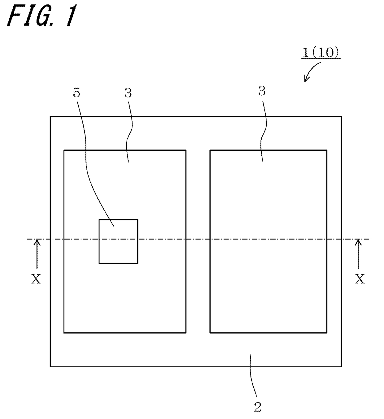
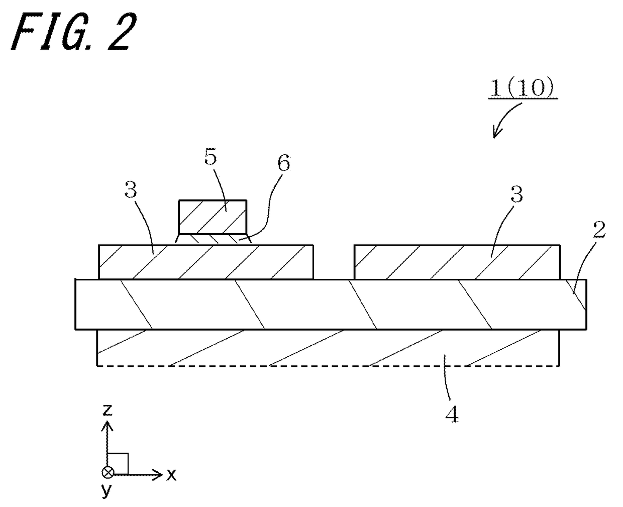
[0021]A circuit board 1 according to an embodiment of the present invention will be described with reference to FIGS. 1 and 2. The circuit board 1 includes an insulating substrate 2, metal circuit sheets 3, and a heat dissipating sheet 4. In the example illustrated in FIGS. 1 and 2, an electronic device 10 includes the circuit board 1 and an electronic component 5. Note that a lower part of the heat dissipating sheet 4 is not shown, as the heat dissipating sheet 4 is thick as described below.

[0022]The insulating substrate 2 is made of an ele...

second embodiment

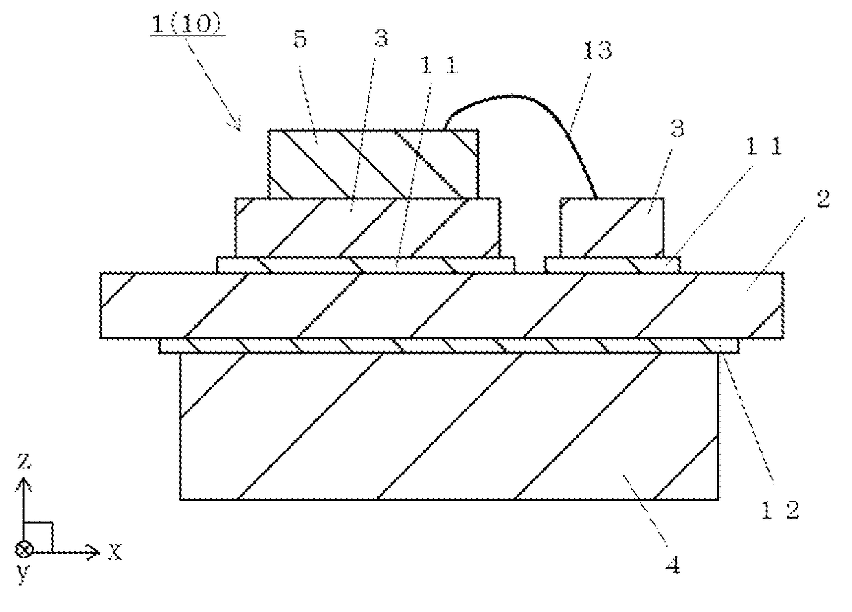
[0048]FIG. 3 is a cross-sectional view of the circuit board 1 according to a second embodiment of the present invention. In the second embodiment, the circuit board 1 includes the insulating substrate 2, the metal circuit sheet 3, the heat dissipating sheet 4, a first brazing material 11, and a second brazing material 12. FIG. 4 is a cross-sectional view of the electronic device 10 according to the second embodiment of the present invention. In the example illustrated in FIG. 4, the electronic device 10 includes the circuit board 1 and the electronic component 5.

[0049]In the circuit board 1 of the second embodiment, the metal circuit sheet 3 is joined by the first brazing material 11 to the upper surface of the insulating substrate 2. The heat dissipating sheet 4 is joined by the second brazing material 12 to the lower surface of the insulating substrate 2. The first brazing material 11 has, at least in an outer portion thereof, a thermal expansion coefficient higher than the therma...


PUM


Abstract

A circuit board includes an insulating substrate; a metal circuit sheet joined to a first principal surface of the insulating substrate; and a heat dissipating sheet made of metal and joined to a second principal surface of the insulating substrate, the second principal surface being opposite the first principal surface. The thickness of the heat dissipating sheet is at least 3.75 times the thickness of the metal circuit sheet. The size of metal grains contained in the heat dissipating sheet is smaller than the size of metal grains contained in the metal circuit sheet, and decreases with increasing distance from the second principal surface of the insulating substrate.

Description

TECHNICAL FIELD[0001]The present invention relates to a circuit board and an electronic device using the same.BACKGROUND ART[0002]Conventionally, circuit boards have been used in electronic devices in which an electronic component, such as an insulated gate bipolar transistor (IGBT) of a power module or a switching module, is mounted. For example, Patent Literature (PTL) 1 discloses a circuit board in which a metal circuit sheet made of copper and formed into a circuit pattern is joined to a first principal surface of an insulating substrate, and a heat dissipating sheet made of copper and configured to dissipate heat generated from an electronic component mounted on the metal circuit sheet is joined to a second principal surface of the insulating substrate.[0003]Generally, in a circuit board such as that described above, the thickness of the heat dissipating sheet is set to be substantially the same as, or slightly less than, the thickness of the metal circuit sheet. This is to bal...

Claims


Application Information

Patent Timeline
IPC IPC(8): H01L23/373H01L23/15H01L21/48
CPCH01L23/3735H01L21/4857H01L23/15H01L2224/48091H01L2224/48227H01L2224/32225H01L2224/49175H01L2924/0002H01L23/36H05K1/0306H05K2201/068H05K1/09H01L23/49844H01L2924/00014H05K1/02H01L23/13H01L23/373H01L23/12H10K50/87H01L23/3736H01L33/641
Inventor KOORIYAMA, SHINICHIOGAWA, NARUTOSHIKONAGAI, MASASHIOCHIAI, KENSOUNIINO, NORITAKA
Owner KYOCERA CORP
Learn More