
Device for correcting hall sensor installation position error of BLDC motor having linear hall sensor, and method thereof

a technology of bldc motor and installation position error, which is applied in the field of bldc motor, can solve the problems of reducing affecting the operation of the motor, so as to reduce the unit cost of the motor, and accurately calculate the rotation angle of the motor

Inactive Publication Date: 2017-12-07
FIRSTEC CO LTD
View PDF0 Cites 24 Cited by
  • Summary
  • Abstract
  • Description
  • Claims
  • Application Information

AI Technical Summary

Benefits of technology

The device and method described in this patent can accurately calculate the rotation angle and speed of a motor, even if there is an error in the installation position of the Hall sensor. This means that the motor can be accurately controlled even if there is an error in the sensor's position. Additionally, this method can reduce the cost of the motor because it does not require physically modifying the error in the sensor's position.

Problems solved by technology

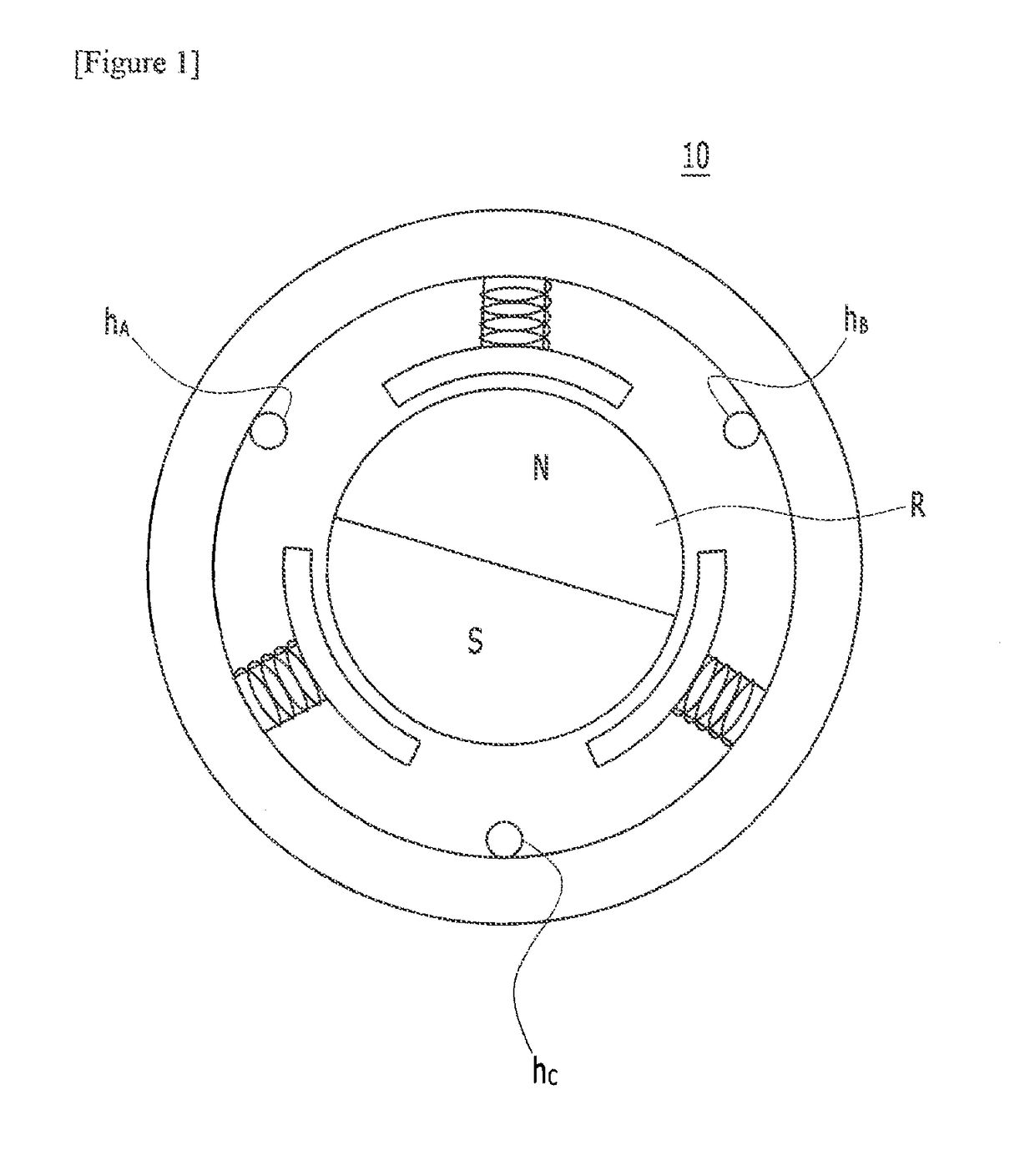
However, since the position of the rotor R is detected by the unit of 60° (degrees) as described above, it is difficult to accurately calculate the rotor's position or rotation speed in the low-speed driving section.
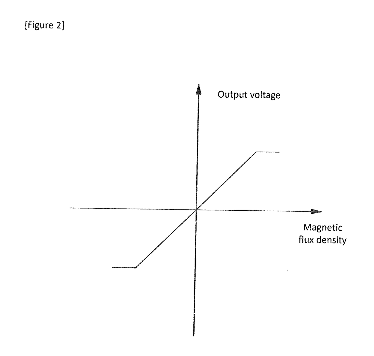
Therefore, when the linear Hall sensor is used for the BLDC motor in the conventional art, if there is an error in the position where the linear Hall sensor is installed, the output voltage of the linear Hall sensor drastically changes.
However, it is very difficult to realistically install the linear Hall sensors at normal positions, without any errors, due to many factors that may occur during the process of manufacturing the motor.
Moreover, reducing an error in installing the linear Hall sensors acts as a factor increasing the unit cost of the motor.
However, if an error occurs in the installation position of the linear Hall sensors, the problem is that it is impossible to accurately measure the position and rotation speed of the motor.

Method used


Image

  • Device for correcting hall sensor installation position error of BLDC motor having linear hall sensor, and method thereof
  • Device for correcting hall sensor installation position error of BLDC motor having linear hall sensor, and method thereof
  • Device for correcting hall sensor installation position error of BLDC motor having linear hall sensor, and method thereof

Examples


Embodiment Construction

[0036]A device and method for correcting a Hall sensor installation position in a BLDC motor with the linear hall sensor(s) according to the present invention will now be described more fully hereinafter with reference to the accompanying drawings. This invention has been described herein using example embodiments of the present invention to carry out the technical idea of the present invention. Therefore, it is to be understood that the scope of the invention is not limited to the disclosed example embodiments. On the contrary, the scope of the invention is intended to include various modifications and alternative arrangements within the capabilities of persons skilled in the art using presently known or future technologies and equivalents. The scope of the claims should be accorded the broadest interpretation so as to encompass all such modifications and similar arrangements.

[0037]Throughout the application, the “position of the motor” accurately means the “position of the rotor o...


PUM


Abstract

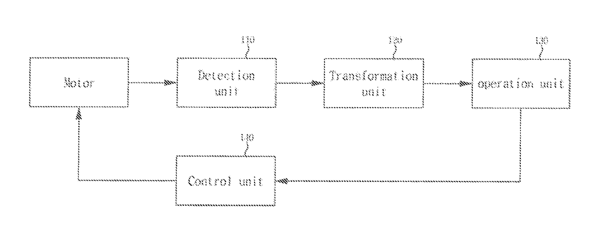
There is provided a device for correcting a Hall sensor installation position error in a BLDC motor which includes a rotor with a permanent magnet, a stator wound with coils to form a magnetic field around the rotor, and three linear Hall sensors installed outwardly around the rotor to generate output signals by the Hall-Effect, the device comprising: a detection unit to detect output signals H1, H2, H3 output from the three linear Hall sensors; a transformation unit to transform the output signals H1, H2, H3 detected in the detection unit to orthogonal two-phase transformation signals Ha, Hb and to transform the transformation signals Ha, Hb to normalized transformation signals Han, Hbn; an operation unit to calculate a rotation angle of the motor from the normalized transformation signals Han, Hbn output in the transformation unit; and a control unit to control the current supplied to the coils winding the stator based on information of the rotation angle transmitted from the operation unit, wherein the transformation unit transforms the output signals H1, H2, H3 to the orthogonal two-phase transformation signals Ha, Hb by Clarke Transformation.

Description

BACKGROUND OF THE INVENTION1. Field of the Invention[0001]The present invention relates to a BLDC motor and more particularly, to a device for correcting a Hall sensor installation position error when a linear Hall sensor is used in the BLDC motor to detect a rotor's position and rotation speed, and a method thereof.2. Description of the Related Art[0002]A BLDC (Brushless Direct Current) motor does not have a brush which an ordinary DC (Direct Current) motor has. A rotor is provided with a permanent magnet is driven by a magnetic force formed by the current supplied to winding coils of a stator. Since the BLDC motor does not have mechanical friction accompanied in a motor structure including the conventional brush, it enables high speed and high efficient driving, reduces noise and vibration and has excellent durability. Due to these merits, the BLDC motors are widely applied in diverse fields, such as many electronic products, medical instruments, military supplies, etc.[0003]The s...

Claims


Application Information

Patent Timeline
Patent Type & Authority Applications(United States)
IPC IPC(8): H02P6/16
CPCH02P6/16H02P21/00
Inventor PARK, KON-KUK
Owner FIRSTEC CO LTD
Learn More