Multi-layer network system and path setting method in multi-layer network

a multi-layer network and network system technology, applied in data switching networks, multiplex communication, fault recovery arrangements, etc., to achieve the effects of reducing control load, high reliability, and high usage efficiency

Active Publication Date: 2017-12-07
NEC CORP
View PDF6 Cites 15 Cited by
  • Summary
  • Abstract
  • Description
  • Claims
  • Application Information

AI Technical Summary

Benefits of technology

[0022]According to a multi-layer network system and a path setting method in a multi-layer network of the present invention, it is possible to decrease a control load in an upper layer network and configure a multi-layer network with high usage efficiency and high reliability.

Problems solved by technology

On the other hand, because there are limitations due to natural laws, the number of factors that can be dynamically controlled is small compared with that in the upper layer network, and the optical network is statically operated and managed substantially.

Method used


Image

  • Multi-layer network system and path setting method in multi-layer network
  • Multi-layer network system and path setting method in multi-layer network
  • Multi-layer network system and path setting method in multi-layer network

Examples


first example embodiment

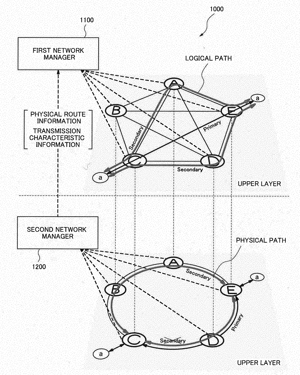
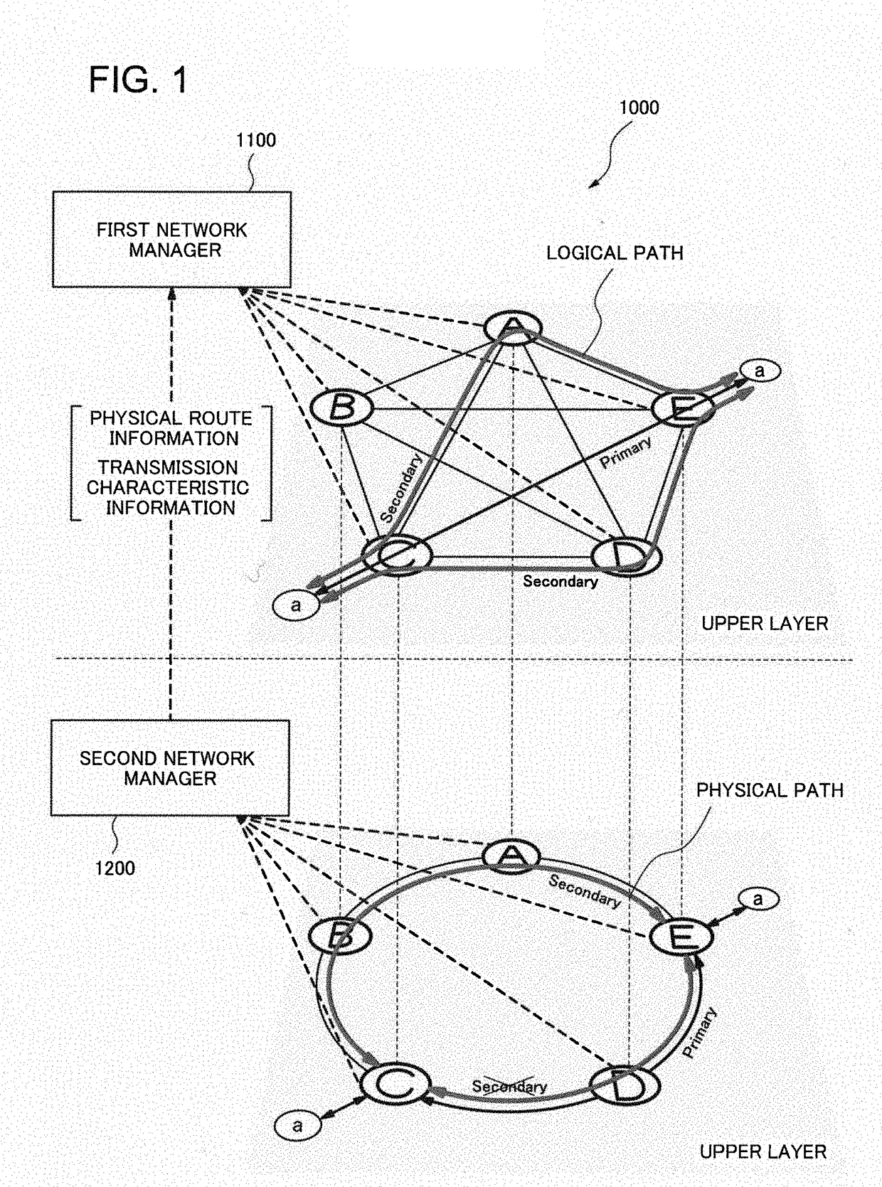
[0033]FIG. 1 is a block diagram schematically illustrating a configuration of a multi-layer network system 1000 according to a first example embodiment of the present invention.

[0034]The multi-layer network system 1000 includes a first network manager 1100 and a second network manager 1200. The first network manager 1100 sets a logical path in a first network layer (an upper layer).

[0035]The second network manager 1200 sets a physical path corresponding to the logical path in a second network layer (a lower layer).

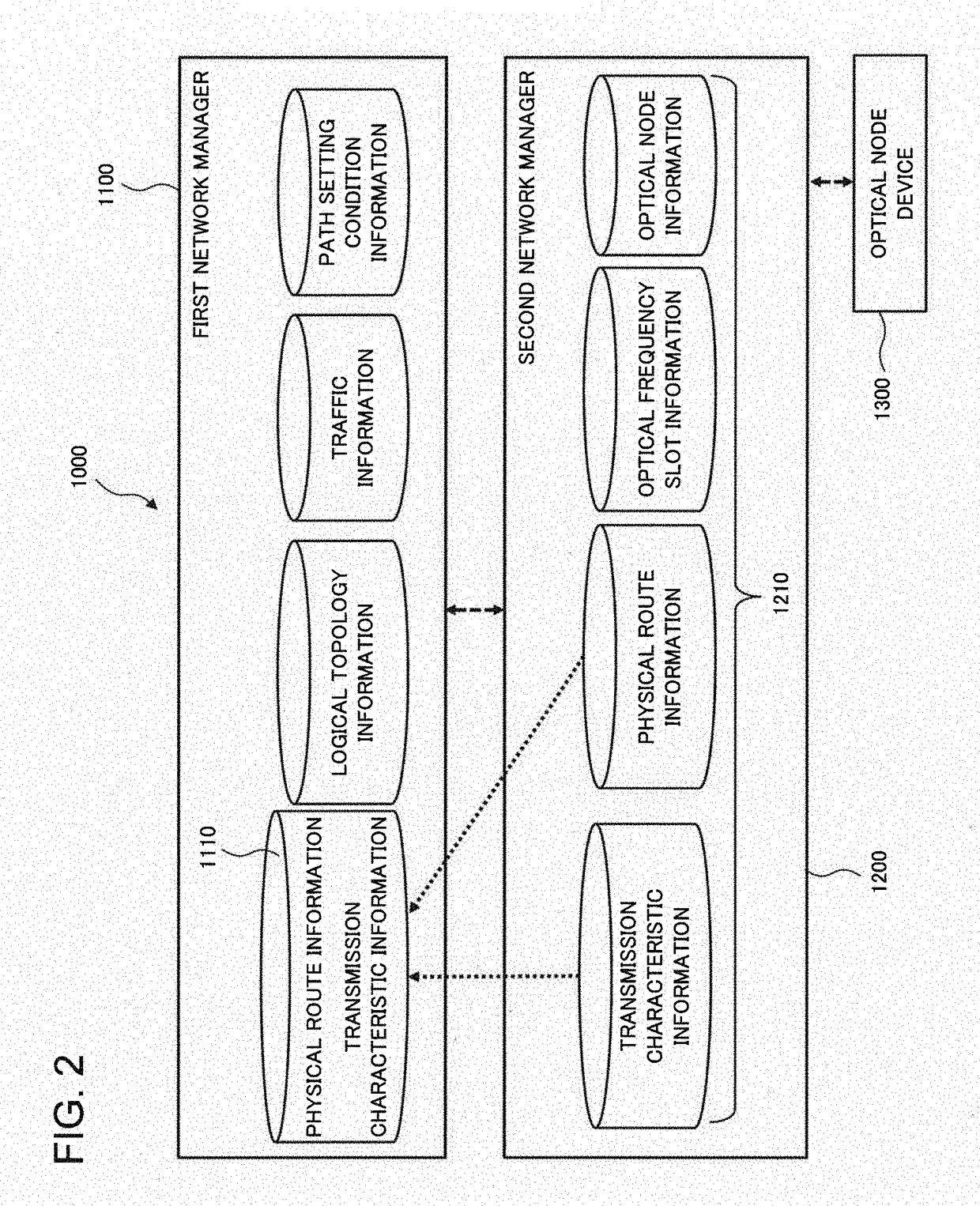
[0036]As illustrated in FIG. 2, the second network manager 1200 includes a network information storage 1210 that stores physical network information including physical route information and transmission characteristic information on the second network layer (lower layer). The first network manager 1100 sets the logical path based on the physical network information. In this case, the first network manager 1100 can be configured to include an acquired information storage 11...

second example embodiment

[0061]Next, a second example embodiment of the present invention will be described. FIG. 4 schematically illustrates a configuration of a multi-layer network system 2000 according to the present example embodiment.

[0062]The configurations of the first network manager 1100 and the second network manager 1200 included in the multi-layer network system 2000 according to the present example embodiment are similar to those of the first example embodiment (see FIG. 2).

[0063]In the present example embodiment, each of a logical path set by the first network manager 1100 and a physical path set by the second network manager 1200 is a redundant system path corresponding to an operational system path. The first network manager 1100 is configured to calculate a shared link cost that is a cost for the logical path with respect to each candidate for the logical path from shared link information on the redundant system path included in the physical route information, and to determine the logical p...

third example embodiment

[0080]Next, a third example embodiment of the present invention will be described. The configuration of a multi-layer network system according to the present example embodiment is similar to that of the multi-layer network system 2000 according to the second example embodiment illustrated in FIG. 4.

[0081]The second network layer (lower layer) constituting the multi-layer network system according to the present example embodiment is configured by an optical network. The second network manager 1200 includes an optical frequency information storage that stores optical frequency slot information indicating a usage situation of optical frequency slots in an optical network (see FIG. 2).

[0082]The second network manager 1200 according to the present example embodiment calculates an optical frequency slot number that indicates the number of optical frequency slots necessary for configuring the physical path determined by the transmission characteristic information. At this time, the first n...


PUM


Abstract

In a multi-layer network, a control load in the upper layer network increases, and the usage efficiency and the reliability of the entire network decrease; therefore, a multi-layer network system according to an exemplary aspect of the present invention includes a first network manager configured to set a logical path in a first network layer; and a second network manager configured to set a physical path corresponding to the logical path, in a second network layer, wherein the second network manager includes a network information storage configured to store physical network information including physical route information and transmission characteristic information on the second network layer, and the first network manager sets the logical path based on the physical network information.

Description

TECHNICAL FIELD[0001]The present invention relates to multi-layer network systems and path setting methods in multi-layer networks, and in particular, to a multi-layer network system that is composed of a plurality of network layers including an optical network, and a path setting method in a multi-layer network.BACKGROUND ART[0002]Because of rapid expansion of mobile traffic and video services, there is a demand for increasing a communication capacity in a core network. The demand for increasing the capacity tends to continue in the future. In order to continuously increase the communication capacity at a limited cost, it is effective to improve usage efficiency of the network by efficiently operating resources of the network. In addition, it is important to increase fault resistance so as to avoid interruptions in service due to occurrence of an unexpected fault.[0003]The current communication network is separated, with respect to each function, into a plurality of layers, each of...

Claims


Application Information

Patent Timeline
Patent Type & Authority Applications(United States)
IPC IPC(8): H04B10/275H04B10/03H04B10/079H04J14/02H04L45/247H04L45/42
CPCH04B10/275H04J14/02H04B10/0795H04B10/03H04L12/437H04J14/0257
Inventor TAKESHITA, HITOSHIFUJISAWA, SHINSUKEHINO, TOMOYUKITAJIMA, AKIO
Owner NEC CORP
Why Eureka
Try Eureka