Local interconnect network bus architecture

a network bus and interconnection technology, applied in the field of electromechanical devices, can solve the problems of high cost of such systems, and disadvantages, and achieve the effects of avoiding electromagnetic compatibility (emc) problems, and reducing the number of devices

Active Publication Date: 2017-12-14
MELEXIS TECH NV
View PDF19 Cites 17 Cited by
  • Summary
  • Abstract
  • Description
  • Claims
  • Application Information

AI Technical Summary

Benefits of technology

[0012]It is an object of embodiments of the present invention to provide devices and methods for allowing a large number of slave nodes, e.g. more than 15 slave nodes, to be connected to a single master node via a single, connected LIN bus network architecture, e.g. without introducing a requirement for more data line ports on the master node for an increasing number of slave nodes.

Problems solved by technology

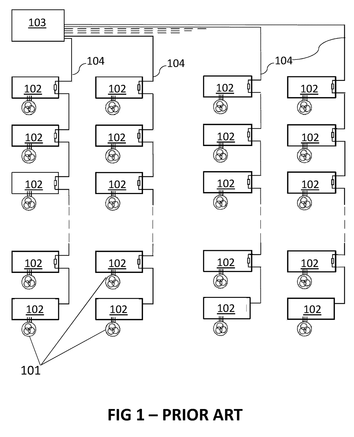
However, such direct control, as known in art, may require a dedicated control wire for each controlled device connecting to the control module, and may thus have a disadvantageous cost, system complexity, resistive losses and / or interference risk associated therewith due to the wires and connectors required.
A high cost of such system may be, at least partially, associated with the additional requirements for supporting multiple input and output (I / O) ports, higher memory requirements and more advanced and / or faster processing capabilities to determine the correct interface connection for routing a particular message and for handling inbound and outbound traffic on multiple busses simultaneously.
Furthermore, due to the large number of wired connections of the ECU that are required to control multiple LIN buses, electromagnetic compatibility (EMC) issues may arise due to electric field coupling, e.g. capacitive coupling, between the wires.
While such EMC issues could be resolved by including additional decoupling capacitors, this would also disadvantageously increase the system.
The EMC issues may need to be solved by additional capacitors thereby increasing the total system cost.
Moreover, the space requirements for the wire harness, particularly in the direct vicinity of the central ECU, may be high, such that other design parameters may be disadvantageously affected, e.g. introducing constraints in mechanical design.

Method used


Image

  • Local interconnect network bus architecture
  • Local interconnect network bus architecture
  • Local interconnect network bus architecture

Examples


Embodiment Construction

[0047]The present invention will be described with respect to particular embodiments and with reference to certain drawings but the invention is not limited thereto but only by the claims. The drawings described are only schematic and are non-limiting. In the drawings, the size of some of the elements may be exaggerated and not drawn on scale for illustrative purposes. The dimensions and the relative dimensions do not correspond to actual reductions to practice of the invention.

[0048]Furthermore, the terms first, second and the like in the description and in the claims, are used for distinguishing between similar elements and not necessarily for describing a sequence, either temporally, spatially, in ranking or in any other manner. It is to be understood that the terms so used are interchangeable under appropriate circumstances and that the embodiments of the invention described herein are capable of operation in other sequences than described or illustrated herein.

[0049]Moreover, t...


PUM


Abstract

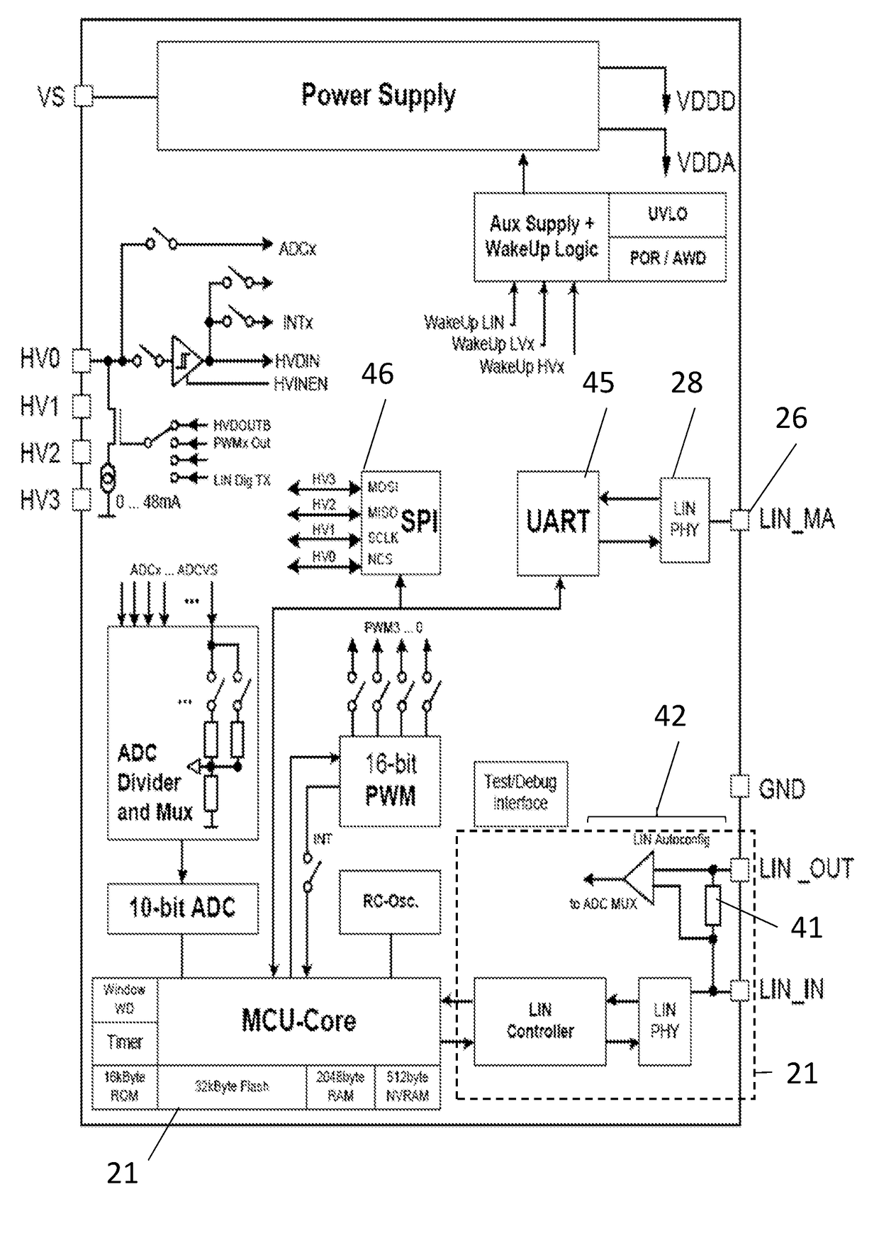
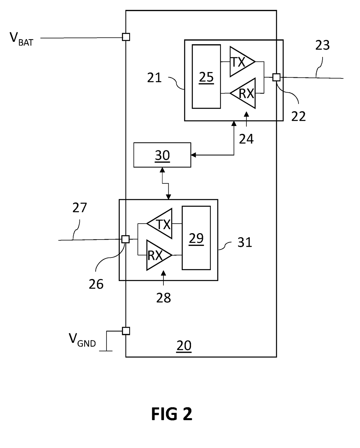
The present invention relates to an integrated circuit device for controlling LIN slave nodes based on a control signal transmitted by a LIN master control device. The IC device comprises a slave node circuit for processing the control signal when received in the form of a LIN message frame via a first data line terminal. The IC device also comprises a master node circuit for processing further control signals to be transmitted in the form of LIN message frames via a second data line terminal to the LIN slave nodes. The IC device also comprises a processing unit for controlling the LIN slave nodes based on the control signal by composing the further control signals.

Description

FIELD OF THE INVENTION[0001]The invention relates to the field of electronic devices for data communication via a serial network bus system, and more specifically to electronic devices and systems conforming to the Local Interconnect Network (LIN) bus standard and related methods.BACKGROUND OF THE INVENTION[0002]The Local Interconnect Network (LIN) bus standard is an open protocol defined for use in communicating between a number of distributed modules. Such communication standards may typically refer to systems in which a plurality of similar modules are used on a common bus line, and in which each module may need to be addressed individually. A LIN bus system may comprise a master node that is connected via a wired connection, e.g. by a single data wire forming a common signal conductor, to at least one slave node. Thus, the master node and slave node(s), connected by the data wire, form a network cluster. These slave devices may form control components associated with identical a...

Claims


Application Information

Patent Timeline
Patent Type & Authority Applications(United States)
IPC IPC(8): H04L12/40H04L12/403
CPCH04L12/40006H04L2012/40234H04L12/403H04L2012/40273
Inventor BENDER, MICHAELMCKENNA, PHILIPFREITAG, THOMAS
Owner MELEXIS TECH NV
Why Eureka
Try Eureka