Energy storage device
a technology of energy storage and energy storage devices, which is applied in the direction of cell components, sustainable manufacturing/processing, and final product manufacturing, etc., can solve the problem of small capacity of energy storage devices, and achieve the effect of increasing the capacity of energy storag
- Summary
- Abstract
- Description
- Claims
- Application Information
AI Technical Summary
Benefits of technology
Problems solved by technology
Method used
Image

Examples
first embodiment
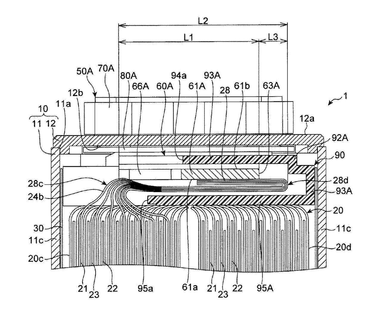
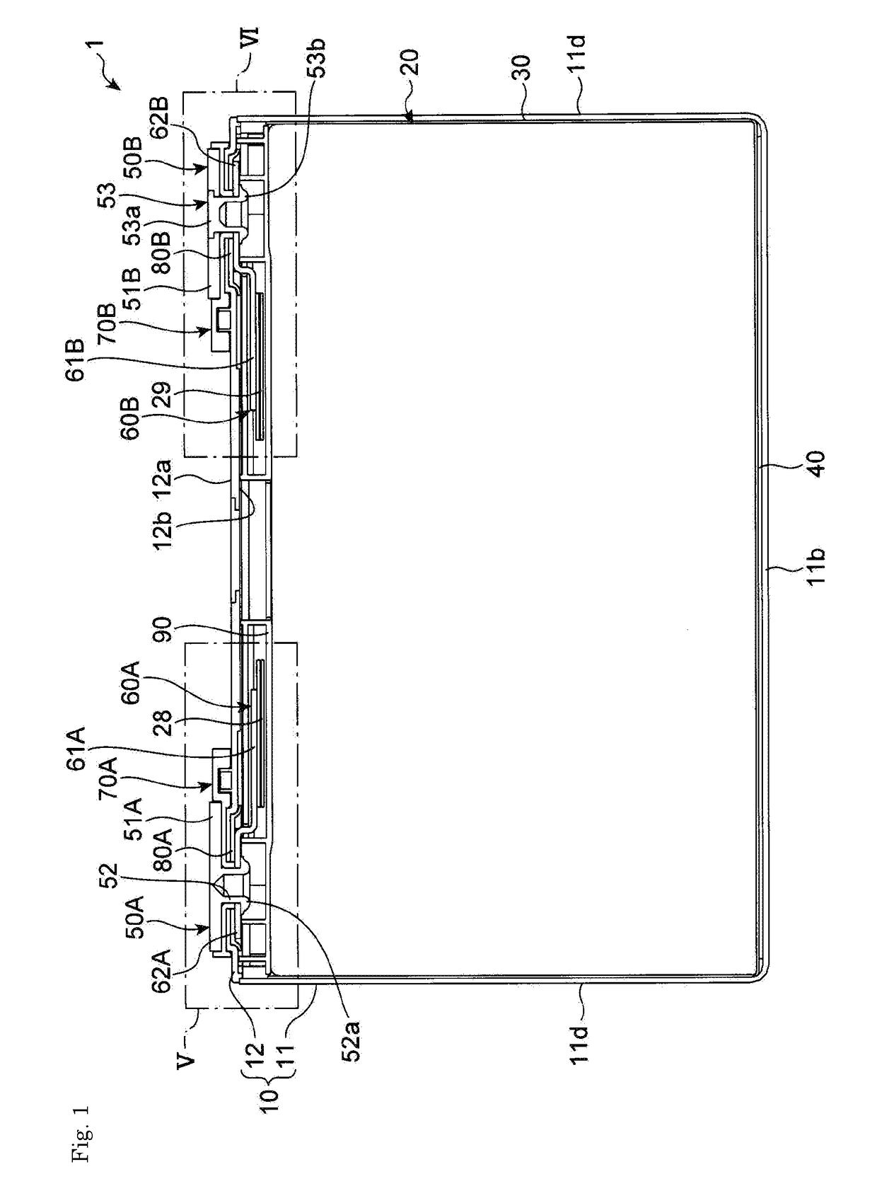
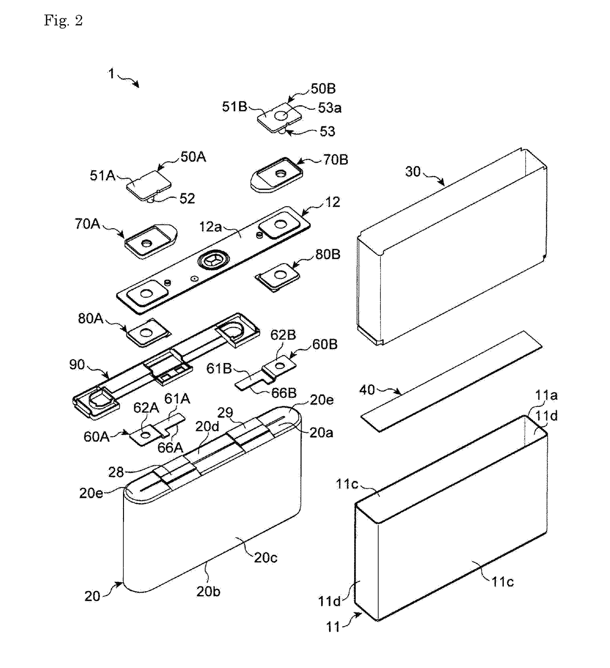
[0031]FIG. 1 and FIG. 2 show a lithium ion secondary battery (hereinafter simply referred to as a battery) 1 according to a first embodiment of the present invention.
[0032](Overall Configuration)
[0033]With reference to FIG. 1 and FIG. 2, the battery 1 includes an outer case 10, an electrode assembly 20, an insulation sheet 30, a bottom spacer 40, an external terminal 50A for a positive electrode and an external terminal 50B for a negative electrode, positive and negative current collectors 60A, 60B, upper packings 70A, 70B, lower packings 80A, 80B, and an upper spacer 90.
[0034]The outer case (case) 10 includes a case body 11, and a lid 12 which closes an opening 11a of the case body 11. In this embodiment, the case body 11 and the lid 12 are made of aluminum or an aluminum alloy. The case body 11 has a rectangular plate-like bottom wall portion 11b, a pair of long-side wall portions 11c, 11c which is raised from long sides of the bottom wall portion 11b, and a pair of short-side wal...
second embodiment
[0076]FIG. 15 shows a battery 1 of a second embodiment. The second embodiment differs from the first embodiment with respect to a point that second bent portions 28d, 29d are bent below welded portions 61A, 61B of current collectors 60A, 60B respectively. The second embodiment can acquire the same manner of operation and the same advantageous effects as the first embodiment. Further, in the second embodiment, total lengths of current collecting tabs 28, 29 can be set as short as possible and hence, electric resistance at the time of energization can be made small. Still further, there is no possibility that the current collecting tabs 28, 29 which are connected to the current collectors 60A, 60B respectively are brought into contact with an outer case 10 and hence, as shown in the drawing, it is unnecessary to arrange an upper spacer 90 in the inside of the outer case 10. Alternatively, in the second embodiment, it may be possible to use an upper spacer 90 where a current collector ...
third embodiment
[0077]FIG. 16 shows a battery 1 of a third embodiment. The third embodiment differs from the first embodiment with respect to a point that current collecting tabs 28, 29 are joined to upper surfaces 61b of welded portions 61A, 61B of current collectors 60A, 60B, and edges 63A, 63B of the welded portions 61A, 61B are utilized for bending of second bent portions 28d, 29d.
[0078]As shown in FIG. 17, in assembling the current collectors 60A, 60B to the current collecting tabs 28, 29, in the same manner as the first embodiment, an electrode assembly 20 is disposed transversely such that a first straight line portion 20c side is positioned downward, and the current collectors 60A, 60B are disposed such that swaged portions 62A, 62B are positioned above the welded portions 61A, 61B respectively. Further, the electrode assembly 20 is disposed on an edge 63A, 63B side of the welded portions 61A, 61B, and the current collecting tabs 28, 29 are disposed on an upper surfaces 61b side of the wel...
PUM
| Property | Measurement | Unit |
|---|---|---|
| size | aaaaa | aaaaa |
| height | aaaaa | aaaaa |
| shape | aaaaa | aaaaa |
Abstract
Description
Claims
Application Information
 - R&D
- Intellectual Property
- Life Sciences
- Materials
- Tech Scout
- Unparalleled Data Quality
- Higher Quality Content
- 60% Fewer Hallucinations
Browse by: Latest US Patents, China's latest patents, Technical Efficacy Thesaurus, Application Domain, Technology Topic, Popular Technical Reports.
© 2025 PatSnap. All rights reserved.Legal|Privacy policy|Modern Slavery Act Transparency Statement|Sitemap|About US| Contact US: help@patsnap.com