
Processing device for rail systems in urban areas

A technology for treatment devices and urban areas, applied in the direction of fixed grinding wheel devices, rails, rail maintenance, etc., can solve the problems of high total weight, increase noise pollution and exhaust gas pollution, movable treatment devices cannot be used, etc., to achieve high friction coefficient, the effect of avoiding conversion loss

Inactive Publication Date: 2020-09-18
林辛格工程有限责任公司
View PDF16 Cites 2 Cited by
  • Summary
  • Abstract
  • Description
  • Claims
  • Application Information

AI Technical Summary

Problems solved by technology

The disadvantage here, however, is that, with the attendant larger dimensions and higher overall weight of the device, such a mobile processing device cannot be used in urban areas, especially since the railway embankments there are not designed for such high wheel set loads and due to the existing infrastructure only limited structural heights are feasible
Furthermore, installations of this type increase unwanted or impermissible noise pollution and exhaust air pollution in urban areas, especially in metro shafts

Method used


Image

  • Processing device for rail systems in urban areas
  • Processing device for rail systems in urban areas
  • Processing device for rail systems in urban areas

Examples


Embodiment Construction

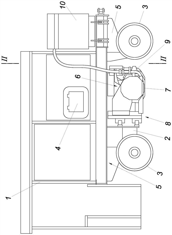
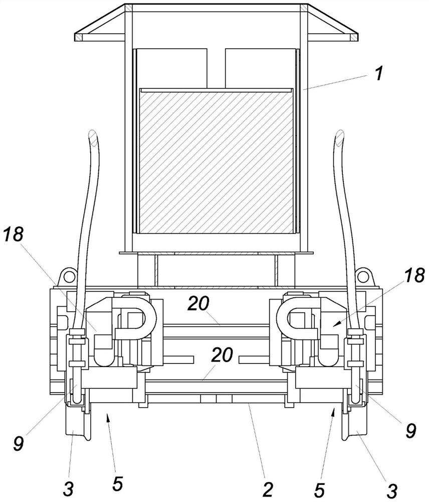
[0015] An embodiment of the treatment device according to the invention can have a vehicle frame 1, a chassis 2 with wheels 3, an electrical energy store 4, an energy distribution system, a travel drive 5, a treatment drive 6, a treatment tool 7, a feed drive 8 and Suction device 9 with chip collection container 10 .

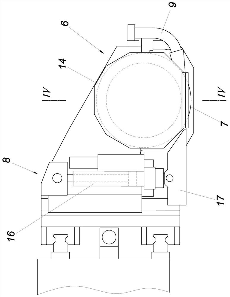
[0016] Figure 4 A processing tool 7 , which can be designed, for example, as a pot-shaped milling head or also as a grinding wheel, is shown mounted on the shaft 10 by means of bolts and supported in a floating manner on the shaft 10 . Furthermore, the shaft 10 can be arranged in a housing 11 and partially surrounded circumferentially by the pot-shaped treatment tool 7 so that an imaginary shaft extending normal to the longitudinal axis of the shaft and passing through the closer-located bearing 12 can be arranged. The plane intersects the processing tool 7 . For protection, the processing tool 7 can be surrounded by a cover or cover 14 which is open downward...


PUM


Abstract

The invention describes a processing device for rail systems in urban areas, having a travel drive (5), a processing drive (6) and a contour-defining, rotationally driven processing tool (7) mounted in a floating manner on a shaft (10) arranged in a housing (11), wherein the processing tool (7), the housing (11) and the shaft (10) are arranged on a chassis (2) having wheels (3) and can be placed by a feed drive (8) against a rail head (13) to be processed. In order to configure a device of the type described at the outset in such a way that it has a compact design such that it can be used forprocessing rail systems in urban areas both above ground and below ground, it is proposed that the processing tool (7) is of pot-shaped design and attached end-side by its base to the shaft (10), wherein the circumferential surface of the cutting edge-bearing flank of the processing tool (7) at least partially circumferentially encloses the shaft (10) and the closer-situated shaft bearing (12).

Description

technical field [0001] The invention relates to a treatment device for rail installations in urban areas, which has a travel drive, a treatment drive and a contoured, rotationally driven and suspended mount in a housing. The processing tool on the shaft, wherein the processing tool, the housing and the shaft are arranged on the chassis and can be mounted on the rail head to be processed by means of a feed drive. Background technique [0002] Known mobile devices, especially rail vehicles, for handling the railway bed or bed of a standard gauge railway And have processing driver, feeding driver and processing tool (patent document WO2013109945 A1). Similar devices are also shown, for example, in patent documents GB 255176 A, US 4615150 A, US 4583327 A or US 1988138 A. Due to the high reaction forces generated during the treatment, the treatment device must on the one hand have a correspondingly high rigidity and on the other hand have a powerful energy supply, which is usu...

Claims


Application Information

Patent Timeline
IPC IPC(8): E01B31/12B24B45/00B23C3/00B24B19/00
CPCB23C3/005B24B19/004E01B31/12
Inventor W.孔普休伯M.格劳尔
Owner 林辛格工程有限责任公司
Learn More