Unlock instant, AI-driven research and patent intelligence for your innovation.

Switching power supply device

a power supply device and power supply technology, applied in the direction of electric variable regulation, process and machine control, instruments, etc., can solve the problems of difficult detection of zero current by the comparator b>14, /b>, etc., and achieve the effect of preventing a decrease in power factor

Active Publication Date: 2017-12-21
FUJI ELECTRIC CO LTD
View PDF0 Cites 7 Cited by
  • Summary
  • Abstract
  • Description
  • Claims
  • Application Information

AI Technical Summary

Benefits of technology

The present invention is a switching power supply device that aims to prevent a decrease in power factor even when the load becomes light. To achieve this, the device includes a load state detection part, a zero-current detection and frequency reduction part, a restart timer, and a timer adjustment part. The load state detection part detects the weight of the load to which the output direct current voltage is provided. The zero-current detection and frequency reduction part reduces the switching frequency of the switching element by delaying the turn-ON timing of the switching element. The restart timer turns the switching element ON when the zero-current detection and frequency reduction part is unable to do so. The timer adjustment part lengthens the restart time of the restart timer so as to synchronize with the turn-ON timing of the switching element that has been delayed by the zero-current detection and frequency reduction part. Overall, the present invention prevents a decrease in power factor when the load is light and provides many practical effects.

Problems solved by technology

However, even if the turn-ON timing of the switching element 4 is controlled by controlling the number of times zero current detection is performed by the frequency reduction circuit20 in the above-described manner, it may be difficult for the comparator 14 to detect zero current, depending on the size of the input alternating current voltage and the design specifications of the switching power supply device 1.

Method used


Image

  • Switching power supply device
  • Switching power supply device
  • Switching power supply device

Examples


Embodiment Construction

[0054]A switching power supply device according to an embodiment of the present invention will be explained hereafter with reference to the drawings.

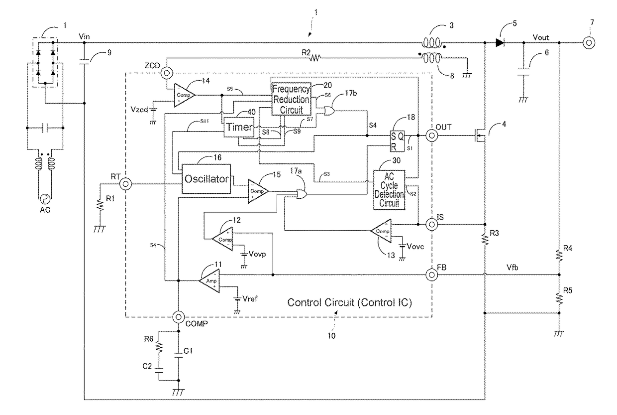
[0055]FIG. 1 is a schematic configuration diagram of a switching power supply device 1 according to an embodiment of the present invention. Constituent portions similar to those of the conventional switching power supply device 1 shown in FIG. 7 are assigned the same reference characters and descriptions thereof are omitted.

[0056]This switching power supply device 1 is characterized by being configured so as to set the turn-ON timing of a switching element 4 via a restart timer 40 so as to match the turn-ON timing of the switching element 4 via zero current detection by changing a restart time of the restart timer 40 in accordance with the weight of a load. Specifically, the switching power supply device 1 is characterized by including a timer adjustment part that lengthens the restart time of the restart timer 40 so as to match the tur...


PUM


Abstract

The present invention provides, in one aspect, a restart timer that turns a switching element ON when it is not possible to turn the switching element ON via a zero-current detection and frequency reduction part, and specifically includes: a frequency reduction part that reduces a switching frequency of the switching element by delaying the turn-ON timing of the switching element by the zero-current detection and frequency reduction part when a light load state is detected; and a timer adjustment part that lengthens the restart time of the restart timer by synchronizing with the turn-ON timing of the switching element that was delayed by the frequency reduction part.

Description

BACKGROUND OF THE INVENTIONTechnical Field[0001]The present invention relates to a switching power supply device that includes a function that improves the power factor by reducing the switching frequency when the load is light, and particularly relates to a switching power supply device that is able to prevent a decrease in the power factor even when it is not possible to determine the turn-ON timing of a switching element via zero current detection when operating at a reduced frequency.Background Art[0002]Patent Documents 1, 2, and the like, for example, introduce in detail, from among quasi-resonant switching power supply devices that generate a prescribed output direct current voltage Vout by switching an input voltage Vin, switching power supply devices that include a power factor correction function that improves the power factor when the load is light in particular.[0003]FIG. 7 is a schematic configuration diagram that shows one example of a switching power supply device 1 th...

Claims


Application Information

Patent Timeline
Patent Type & Authority Applications(United States)
IPC IPC(8): H02M3/335H02M1/42H02M3/158H02M3/156
CPCH02M3/33507H02M3/33569H02M3/158H02M3/1588H02M3/156H02M1/4225H02M1/4258Y02B70/10Y02P80/10H02M1/0032H02M1/0058H02M3/01
Inventor SUGAWARA, TAKATO
Owner FUJI ELECTRIC CO LTD