Spun-Blown Non-Woven Web

a non-woven, fiber-based technology, applied in the direction of spinnerette packs, spinning methods, weaving, etc., can solve the problems of inability to extrude smaller fibers, extreme weak strength of conventional meltblown fibers,

Active Publication Date: 2018-01-04
BIAX FIBERFILM CORP
View PDF3 Cites 8 Cited by
  • Summary
  • Abstract
  • Description
  • Claims
  • Application Information

AI Technical Summary

Benefits of technology

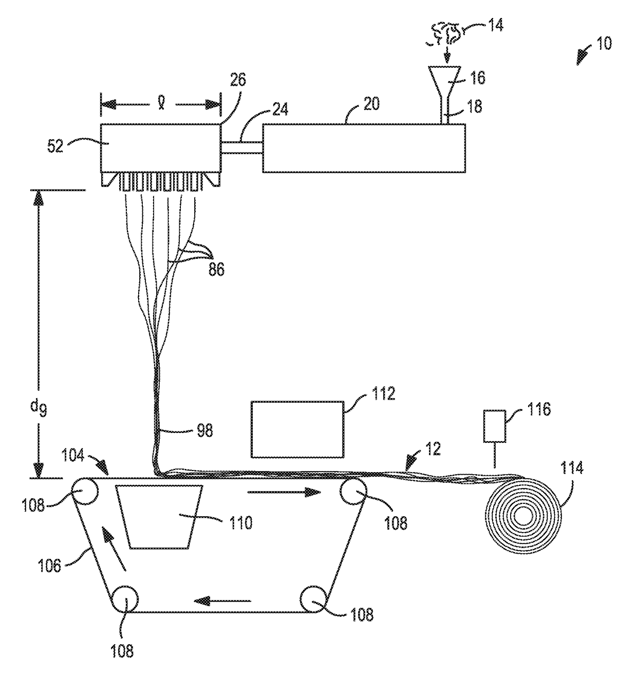
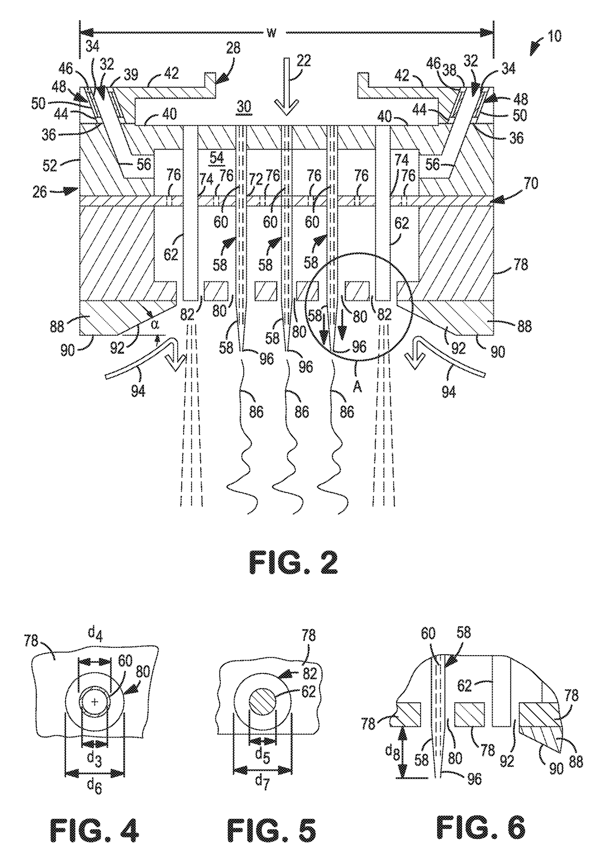
[0006]Briefly, this invention relates to an apparatus and a process for forming a Spun-Blown® non-woven web, and the web itself. The apparatus for producing a Spun-Blown® non-woven web includes a die block having an inlet for receiving a molten material which communicates with a cavity. The die block also has a gas passage through which pressurized gas can be introduced. The gas passage has an inside diameter. An insert is positioned in the gas passage and has an inside diameter and an outside diameter. A major portion of the outside diameter is smaller than the inside diameter of the gas passage to form an air chamber therebetween. The apparatus also includes a spinnerette secured to the die block which has a gas chamber isolated from the cavity. The spinnerette also has a gas passageway which connects the gas chamber to the gas passage. A plurality of nozzles and a plurality of stationary pins are secured to the spinnerette. The plurality of nozzles and the plurality of stationary pins are grouped into an array of a plurality of rows and a plurality of columns, having a periphery. Each of the plurality of nozzles is connected to the cavity. The apparatus further includes a gas distribution plate secured to the spinnerette which has a plurality of first, second and third openings formed therethrough. Each of the first openings surrounds one of the nozzles, each of the second openings surrounds one of the stationary pins, and each of the third openings is located adjacent to the first and second openings. The apparatus also includes an exterior member secured to the gas distribution plate. The exterior member has a plurality of first and second enlarged openings formed therethrough. Each of the first enlarged openings surrounds one of the nozzles and each of the second enlarged openings surrounds one of the stationary pins. The array of nozzles and stationary pins has at least one row and at least one column, which are located adjacent to the periphery, being made up of the second enlarged openings. The pressurized gas exits through both the first and second enlarged openings at an adjustable velocity. The molten material is extruded into filaments and each of the filaments is shrouded by the pressurized gas to be attenuated into solid fibers due to the acceleration of the fibers and the quenching effect of the expansion of the pressurized gas. In addition, the periphery around all of the extruded filaments / fibers is shrouded by another pressurized gas curtain to isolate them from the surrounding ambient air, essentially a dual shroud system. Lastly, the apparatus includes a moving surface located downstream of the exterior member onto which the fibers are collected into a Spun-Blown® non-woven web.

Problems solved by technology

However, conventional meltblown fibers are extremely weak in strength due to the high die and air temperatures used in the forming process.
Typically, spunbond-meltblown-spunbond (SMS) non-woven structures are formed because the conventional meltblown fibers do not have the strength necessary to make a one layer fabric.
The problem, up to now, is that no one has been able to find a way to extrude smaller fibers, having a diameter close to those of meltblown fibers, yet having similar strength of spunbond fibers.

Method used


Image

  • Spun-Blown Non-Woven Web
  • Spun-Blown Non-Woven Web
  • Spun-Blown Non-Woven Web

Examples


example 1

[0140]In this example, we were looking at the effect of spinning technology on web properties. Three (3) different non-woven webs were made using the same polymer resin. All three (3) had the same basis weight but each was spun using a different spinnerette design and different processing conditions. As shown in Table 3, sample S-1 was produced using a Biax multi-row spinnerette design that did not have air insulation inserts 34 or an air shrouding curtain (second enlarged openings 82) surrounding the periphery 84 of the first enlarged openings 80. Sample S-2 was produced using a conventional meltblown process which had only one line of nozzles along with inclined air jets. Sample S-3 was produced using the inventive Spun-Blown® process.

[0141]The sample S-3 achieved almost double the machine direction (MD) tensile strength as compared to sample S-1 or sample S-2. Also, one will notice that the fiber diameter of sample S-3 was slightly larger than the fiber diameter of the convention...

example 2

[0144]In this second example, we were comparing a sample produced by the inventive process S-5 to a sample produced by a conventional meltblown process S-4, and to sample produced by a conventional spunbond process S-6. Three (3) samples were made and each had the same basis weight. As shown in Table 4, the properties of sample S-5 were about half-way between the properties of the conventional meltblown web S-4 and the spunbond web S-6. Table 3 also shows that the air permeability of the sample S-5 (using our inventive process) falls almost half-way between the conventional meltblown sample S-4 and the conventional spunbond sample S-6. This proves that our new technology is capable of producing Spun-Blown® non-woven webs that have fine fiber diameters, comparable to meltblown fibers, yet strong as compared to spunbond fibers.

[0145]Referring to FIG. 13, the machine direction (MD) tensile strength of the Spun-Blown® non-woven web 12 of this invention (sample S-5) was more than double ...


PUM

PropertyMeasurementUnit
diameteraaaaaaaaaa
elongationaaaaaaaaaa

Abstract

A spun-blown non-woven web is disclosed which is formed from a plurality of fibers formed from a single polymer having an average fiber diameter ranging from between about 0.5 microns to about 50 microns; a basis weight of at least about 0.5 gsm; a tensile strength, measured in a machine direction, ranging from between about 20 g to about 4,200 g; a ratio of tensile strength, measured in the machine direction, to basis weight of at least about 20:1; and a ratio of percent elongation, measured in the machine direction, to fiber diameter of at least about 15.

Description

CROSS REFERENCE TO RELATED APPLICATION[0001]This application claims priority to pending non-provisional patent application Ser. No. 14 / 271,675, filed May 7, 2014, and entitled: “A NON-WOVEN WEB”.FIELD OF THE INVENTION[0002]This invention relates to a Spun-Blown® non-woven web.BACKGROUND OF THE INVENTION[0003]Conventional meltblown fibers can be manufactured with very fine diameters, in the range of less than 1 micron to about 10 microns. These fine diameters are very advantageous in forming various kinds of non-woven fabrics. However, conventional meltblown fibers are extremely weak in strength due to the high die and air temperatures used in the forming process. To the contrary, spunbond fibers can be manufactured to be very strong but have a much larger diameter, in the range of from about 15 to about 50 microns. Fabrics formed from spunbond are less opaque and tend to exhibit a rough surface since the fiber diameters are quite large. Typically, spunbond-meltblown-spunbond (SMS) n...

Claims


Application Information

Patent Timeline
Patent Type & Authority Applications(United States)
IPC IPC(8): D01D5/098B29C48/05B29C48/345D04H1/56D04H3/005D04H3/16
CPCD01D5/0985B29C47/0014D04H3/16D04H1/56D04H3/005B29C47/30D04H1/72D04H3/03D01D4/025D01F6/06Y10T442/609B29C48/05B29C48/345D04H1/492
Inventor BROWN, DOUGLAS B.STARK, JEFFREY D.HASSAN, MOHAMMAD A.
Owner BIAX FIBERFILM CORP
Why Eureka
Try Eureka