Refrigerant Compressor System

Active Publication Date: 2018-01-04
BITZER KUEHLMASCHINENBAU GMBH
View PDF4 Cites 0 Cited by
  • Summary
  • Abstract
  • Description
  • Claims
  • Application Information

AI Technical Summary

Benefits of technology

The invention solution improves the reliability of refrigerant compressor systems by allowing a second central processing unit to take control and continue operating the system in case of a failure in the first unit. This eliminates the need for immediate repair or replacement of the first unit, reducing downtime and improving overall efficiency.

Problems solved by technology

These have the problem that they are usually used in an environment in which a failure of the refrigerant compressor system can entail considerable financial damages.
For example, refrigerant compressor systems of this kind are used in large chilling systems, and a failure of a refrigerant compressor system can result in considerable damage to the chilled goods that are to be chilled in the chilling systems.

Method used


Image

  • Refrigerant Compressor System
  • Refrigerant Compressor System
  • Refrigerant Compressor System

Examples


Embodiment Construction

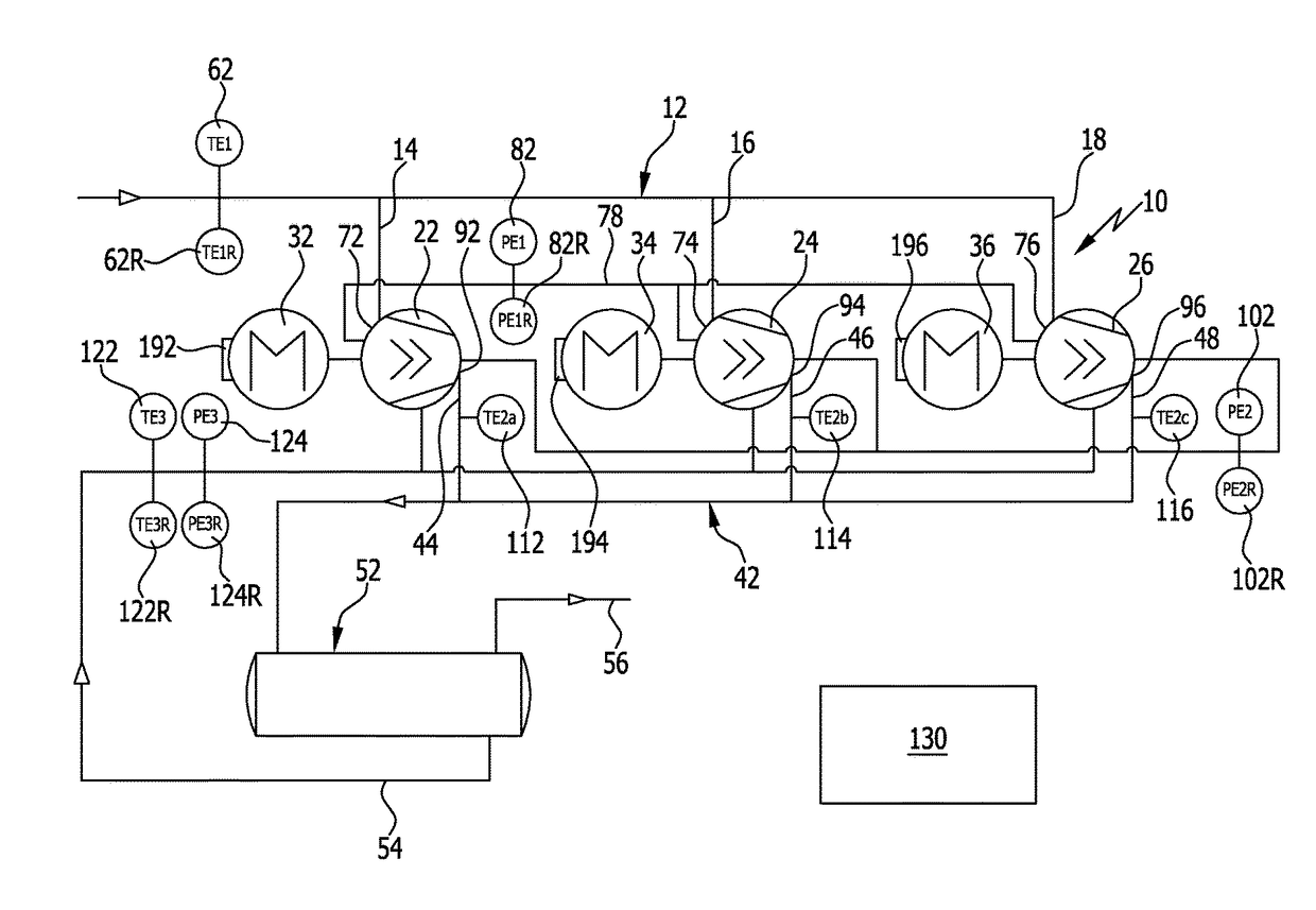
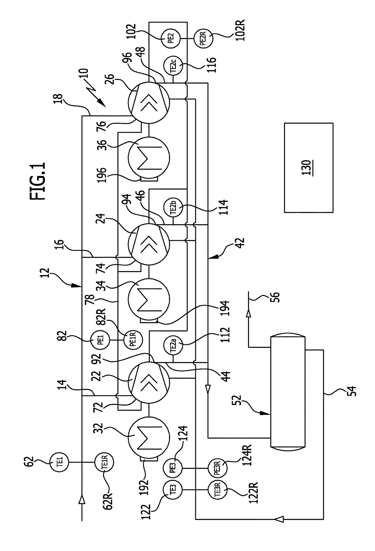
[0060]A refrigerant compressor system which is schematically illustrated in FIG. 1, being designated 10 as a whole, is arranged in a refrigerant circuit and includes a first refrigerant line 12 that conducts expanded refrigerant, which is supplied for example from an expansion device to a heat exchanger associated therewith, neither of which is illustrated in FIG. 1.

[0061]In the case of the illustrated refrigerant compressor system 10, the first refrigerant line 12 includes three supply lines 14, 16, 18, each of which leads to a refrigerant compressor 22, 24, 26 that is respectively driven by a separate motor 32, 34, 36, preferably an electric motor, and compresses the refrigerant which is moved through the refrigerant line 12 to a higher pressure than in the first refrigerant line 12, wherein this higher pressure is typically an intermediate pressure or a high pressure.

[0062]The compressed refrigerant is conducted away out of the respective refrigerant compressor 22, 24, 26 through...


PUM


Abstract

In order to improve the operational reliability of a refrigerant compressor system that includes a first refrigerant line that conducts expanded refrigerant, a second refrigerant line that conducts compressed refrigerant, at least one refrigerant compressor that is arranged between the first and the second refrigerant line and is driven by a motor, and a control unit for operating the refrigerant compressor system, it is proposed that the control unit should have a first central processing unit and at least one input / output unit for control variables that communicates with the first central processing unit, and that there should be associated with the first central processing unit a second central processing unit which, in the event of a failure of the first central processing unit, takes over the control functions for the purpose of controlling the refrigerant compressor system.

Description

CROSS-REFERENCE TO RELATED PATENT APPLICATION[0001]This application is a continuation of International application number PCT / EP2016 / 054907 filed on Mar. 8, 2016.[0002]This patent application claims the benefit of International application No. PCT / EP2016 / 054907 of Mar. 8, 2016 and German application No. 10 2015 103 730.0 of Mar. 13, 2015, the teachings and disclosure of which are hereby incorporated in their entirety by reference thereto.BACKGROUND OF THE INVENTION[0003]The invention relates to a refrigerant compressor system, in particular for ammonia as the refrigerant, including a first refrigerant line that conducts expanded refrigerant, a second refrigerant line that conducts compressed refrigerant, at least one refrigerant compressor that is arranged between the first and the second refrigerant line and is driven by a motor, and a control unit for operating the refrigerant compressor system.[0004]Refrigerant compressor systems of this kind are known from the prior art.[0005]Th...

Claims


Application Information

Patent Timeline
IPC IPC(8): F25B49/02G05B15/02F25B31/00
CPCF25B49/022G05B15/02F25B2400/075F25B2700/21151F25B2700/21152F25B2700/1933F25B2700/1931F25B2400/23F25B31/004F04B27/24F04B39/121F04B49/065
Inventor SCHULAKS, ANDREAS
Owner BITZER KUEHLMASCHINENBAU GMBH
Why Eureka
Try Eureka