
Dynamic analysis system

a dynamic analysis and system technology, applied in image analysis, image enhancement, 2d-image generation, etc., can solve the problems of not always easy for doctors to recognize abnormal parts, not always easy for doctors to recognize, etc., to accurately find abnormal parts and easily recognize.

Inactive Publication Date: 2018-01-04
KONICA MINOLTA INC
View PDF2 Cites 3 Cited by
  • Summary
  • Abstract
  • Description
  • Claims
  • Application Information

AI Technical Summary

Benefits of technology

The patent describes a system that can accurately detect abnormalities in a person's lungs and display them in a way that doctors can easily recognize them. This helps to improve early detection and diagnosis of lung diseases.

Problems solved by technology

However, it is not always easy for doctors to recognize abnormal parts in the function by visually observing dynamic images.
In such a case too, so far, it is not always easy for doctors to recognize such abnormalities by visually observing dynamic images, and even if doctors can recognize the abnormalities, they can recognize them only sentiently.

Method used


Image

  • Dynamic analysis system
  • Dynamic analysis system
  • Dynamic analysis system

Examples


Embodiment Construction

[0028]Hereinafter, an embodiment of the dynamic analysis system of the present invention is described with reference to the drawings.

[Overall Configuration of Dynamic Analysis System]

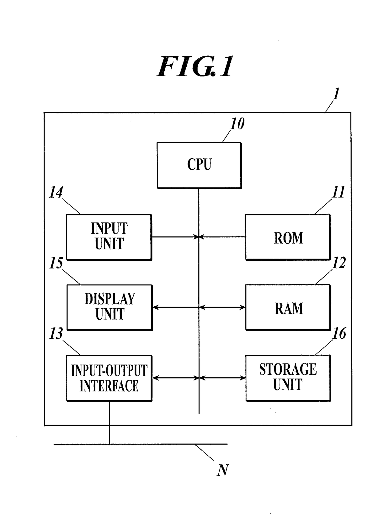
[0029]The overall configuration of a dynamic analysis system 1 according to an embodiment of the present invention is described. FIG. 1 is a block diagram showing the overall configuration of the dynamic analysis system of the embodiment. In the embodiment, as shown in FIG. 1, the dynamic analysis system 1 is constituted of a general-use computer which includes a CPU (Central Processing Unit) 10, a ROM (Read Only Memory) 11, a RAM (Random Access Memory) 12 and an input-output interface 13 connected with one another via a bus, and is connected to a network N via the input-output interface 13.

[0030]The CPU 10 is also connected with: an input unit 14 constituted of a keyboard, a mouse, a touch panel and / or the like; and a display unit 15 constituted of a CRT (Cathode Ray Tube), an LCD (Liquid Crystal Displ...


PUM


Abstract

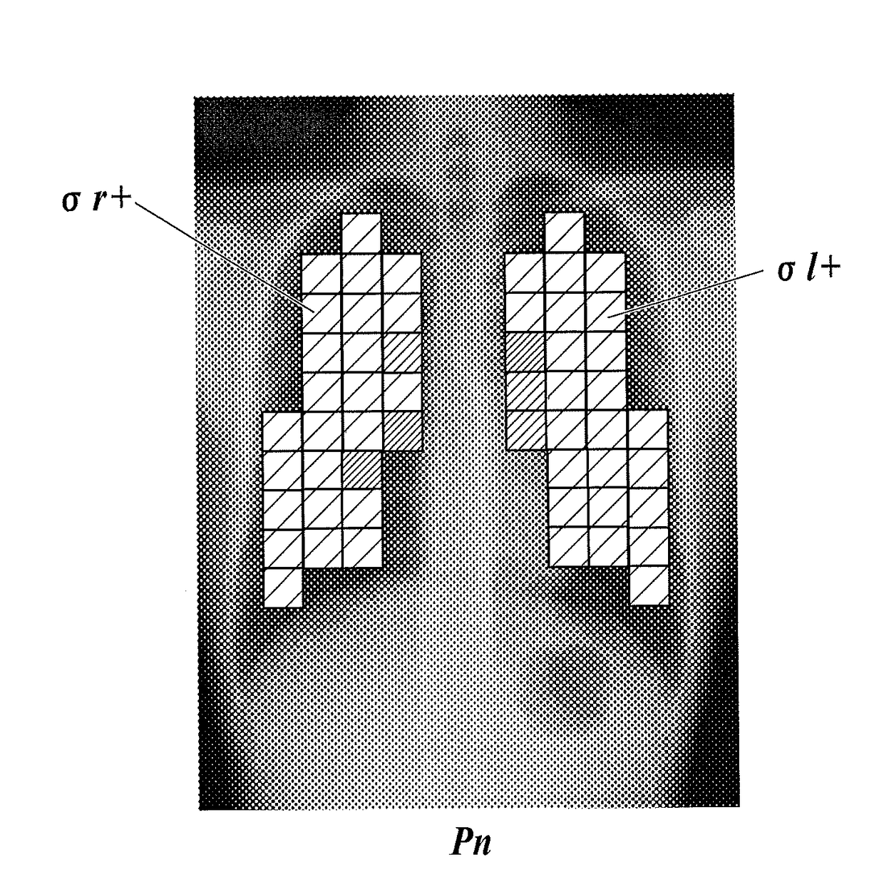
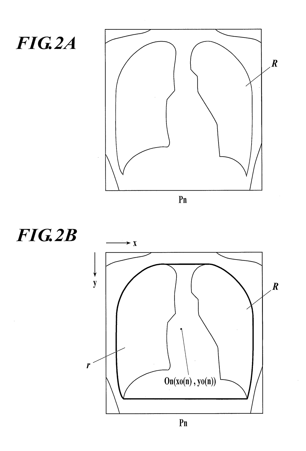
A dynamic analysis system includes a comparing unit and a display unit. The comparing unit extracts a lung field from each of dynamic images obtained by imaging a chest part containing a left lung and a right lung of a subject, specifies a corresponding point in a left part and a corresponding point in a right part of the lung field, and compares characteristic amounts at the respective corresponding points with each other. The display unit displays a result of the comparison made by the comparing unit together with the dynamic images or one of the dynamic images, or displays the result on the dynamic images or the one of the dynamic images.

Description

FIELD OF THE INVENTION[0001]The present invention relates to a dynamic analysis system.DESCRIPTION OF THE RELATED ART[0002]There have been attempts to utilize, for diagnosis, dynamic images of a site which is a target of diagnosis (hereinafter called the “target site”) taken with a semiconductor image sensor, such as an FPD (Flat Panel Detector), instead of radiographic (X-ray) still images of the target site taken with a film / screen or a photostimulable phosphor plate.[0003]More specifically, by making use of high responsivity of a semiconductor image sensor in reading / deleting image data, a dynamic state of the target site is imaged by continuously emitting pulsed radiation from a radiation source in sync with timing of image reading / deletion of the semiconductor image sensor and performing imaging multiple times per second. A series of dynamic images obtained by the imaging are displayed in order, so that doctors can observe a series of motions of the target site.[0004]For exampl...

Claims


Application Information

Patent Timeline
IPC IPC(8): G06T7/00G06T11/20
CPCG06T7/0014G06T2207/30061G06T2207/10004G06T11/206G06T7/0012G06T7/0016G06T2207/10016
Inventor KASAI, SATOSHITSUNOMORI, AKINORI
Owner KONICA MINOLTA INC
Learn More