
Connector device

Active Publication Date: 2018-01-04
SUMITOMO WIRING SYST LTD +1
View PDF2 Cites 6 Cited by
  • Summary
  • Abstract
  • Description
  • Claims
  • Application Information

AI Technical Summary

Benefits of technology

The present invention is a fastening system for electrical connectors in inverters and motors. The system ensures a regular fitting-together of connectors while avoiding bending stress and excessive load. It allows for the proper alignment of connectors and efficient and accurate fitting together. The invention also permits the inverter case to be stacked on the motor case without interfering with the fitting between the connectors. Overall, the invention is simple and effective in achieving a secure and reliable connection between the two electrical systems.

Problems solved by technology

As a result, the connectors may be fitted to each other in a state of being excessively loaded, or the wall surfaces of the cases may be deformed from the connector arranged positions and subjected to bending stress.

Method used


Image

  • Connector device
  • Connector device
  • Connector device

Examples


first embodiment

[0035]the present invention will be described with reference to FIG. 1 to FIG. 15.

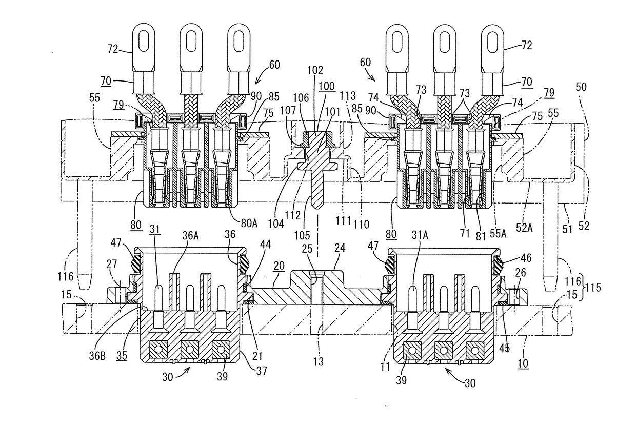
[0036]In this embodiment, as illustrated in FIG. 5 and FIG. 6, motor-side connectors 30 are attached to a motor case 10 constituting a motor. To an inverter case 50 constituting an inverter PCU (hereafter simply referred to as the inverter), inverter-side connectors 60 are attached, vertically facing the motor-side connectors 30. When the inverter case 50 is placed on the motor case 10 and coupled therewith, the motor-side connectors 30 and the inverter-side connectors 60 are attached to each other.

[0037]In the present embodiment, two motor-side connectors 30 and two inverter-side connectors 60 are provided, each having three poles. In other words, there are provided two, right and left, sets of the motor-side connectors 30 and the inverter-side connectors 60 opposing each other.

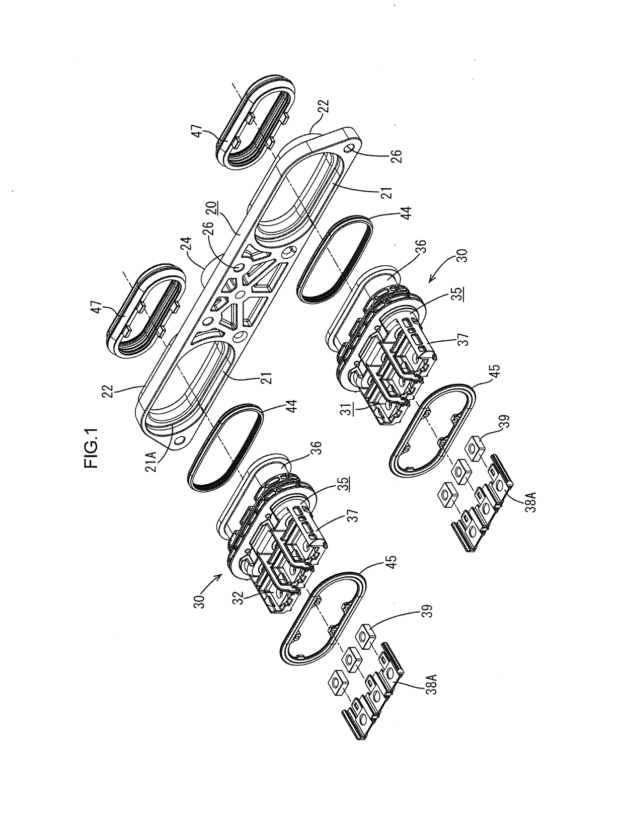
[0038]The motor side will be described. As illustrated in FIG. 1, FIG. 8, and FIG. 10, the motor-side connectors 30 are each ...


PUM


Abstract

A connector device includes a motor-side connector 30 including a motor-side terminal 31, an inverter-side connector 60 including an inverter-side terminal 70, a motor case 10 including the motor-side connector 30, and an inverter case 50 including the inverter-side connector 60, the connectors 30, 60 being fitted together when the inverter case 50 is stacked on and fastened to the motor case 10 using bolts 120. When the fastening of the cases 10, 50 is completed, a predetermined gap is ensured between opposing surfaces 36B, 80A of the connectors 30, 60.

Description

BACKGROUND1. Field of the Invention.[0001]The present invention relates to a connector device used for electrically connecting a motor and an inverter.2. Description of the Related Art.[0002]In electric vehicles and hybrid vehicles, when a motor and an inverter are electrically connected, motor terminals (connector) and inverter terminals (connector) are conventionally connected using a wire harness.[0003]In recent years, for space saving purposes, for example, a connector device has been proposed in which a motor-side connector including motor-side terminals in a motor case and an inverter-side connector including inverter-side terminals in an inverter case are mounted so as to oppose each other, and the inverter case is directly connected to the motor case by bolting, thereby fitting the respective connectors to each other and connecting the respective terminals. An example of the connector device is disclosed in Japanese Patent Application Laid-Open No. 2010-225488.[0004]In the a...

Claims


Application Information

Patent Timeline
IPC IPC(8): H01R13/631H02K5/22H01R13/05B60L3/00B60L11/18H01R13/621H01R12/91H01R13/28H01R13/514H01R13/52
CPCH01R13/6315H01R13/05B60L11/1818B60L3/003H01R13/621H02K5/225H01R13/514H01R12/91H01R13/28H01R13/5202H01R2201/26H02K11/33B60L15/007Y02T10/64
Inventor ISHIBASHI, TAKESHIFUKUSHIMA, TADAHIROHAGIMOTO, TAKAHIROAIBA, TSUKASA
Owner SUMITOMO WIRING SYST LTD
Features
  • Generate Ideas
  • Intellectual Property
  • Life Sciences
  • Materials
  • Tech Scout
  • Unparalleled Data Quality
  • Higher Quality Content
  • 60% Fewer Hallucinations
Learn More