Aircraft light

a technology for aircraft and lights, applied in aircraft control, aircraft components, influencers by generating vortices, etc., can solve problems such as drag generation, and achieve the effects of reducing drag, widening the illumination field, and reducing the proportion of light cones

Inactive Publication Date: 2018-01-11
AIRBUS OPERATIONS LTD
View PDF2 Cites 2 Cited by
  • Summary
  • Abstract
  • Description
  • Claims
  • Application Information

AI Technical Summary

Benefits of technology

[0006]Thus, the present invention may comprise positioning the light in the region where the upwardly extending winglet and the downwardly extending winglet intersect. From an aerodynamic perspective, the join between the upwardly extending winglet and the downwardly extending winglet is not ‘clean’; that is to say flow in this region may be turbulent, with various airflows interacting, all of which may lead to the generation of drag. In view of the fact that airflow in this region is already non-optimal in terms of drag generation, the additional drag generated by including an aircraft light in this region may be lower than the additional drag generated by placing a faired light in a aerodynamically ‘cleaner’ region such as the trailing edge. Locating the light at the join may also facilitate the recessing of the light within existing aircraft structure thereby further reducing the drag generated.
[0010]There may be a gap or void at the join formed between and / or within the upwardly extending winglet and downwardly extending winglet when these are connected together. The join may comprise a join void, said void being defined at least in part by the structure of the upwardly extending winglet and at least in part by the structure of the downwardly extending winglet. The join void may be defined (at least in part) by the fixings that connect the upwardly extending winglet and downwardly extending winglet (for example the first attachment feature and the second attachment feature described below). The join void may be defined at least in part by the aerodynamic fairing that fairs the join. The aircraft light may be located at the join void. The aircraft light may be located within (for example wholly within) the join void. At least part of the aircraft light may be located in the join void. Positioning at least part of the aircraft light within the join void may reduce the drag generated by the aircraft light, by shielding at least part of the aircraft light from the airflow around the wingtip device when the aircraft is in flight.
[0015]The aircraft light may be mounted on the upwardly extending winglet such that at least part or all of the aircraft light is located in the join between the upwardly extending winglet and the downwardly extending winglet. The aircraft light may be directly connected to the upwardly extending winglet and / or the first attachment feature. Thus, it may be that the aircraft light is connected to the rest of the wingtip device (and aircraft) via the upwardly extending winglet. Attaching the aircraft light to the aircraft via the upwardly extending winglet may facilitate maintenance of the aircraft by allowing for removal and / or replacement of the downwardly extending winglet without the need to remove the aircraft light.
[0017]The aircraft light may comprise a light source. The light source may be configured to emit visible light, for example white light. The light source may comprise one or more Light Emitting Diodes (LEDs), High Intensity Discharge (HID) bulbs or other bulbs conventionally used on aircraft. The aircraft light may comprise a housing configured to receive the light source and provide a power supply thereto. The housing may comprise at least one transparent region for allowing the transmission of light from the light source to the surroundings. The housing, for example a portion of the housing exposed to the airflow over the wingtip device when the aircraft is in flight, may be shaped to reduce drag generated by airflow over the housing. For example, the housing may be shaped to continue the aerodynamic profile provided by any adjacent structure of the wingtip device, for example the aerodynamic seal.
[0018]The aircraft light may be located on the outboard side of the winglet. The aircraft light may be configured to provide a light cone directed away from the main fuselage of the aircraft. The aircraft light may be located in the join at the trailing edge of the device. Thus, the light may be adjacent to the trailing edge of the upwardly extending winglet and / or the downwardly extending winglet. Locating the light adjacent to the trailing edge of the device may provide a wider field of illumination by reducing the proportion of the light cone obstructed by the aircraft structure.
[0025]The aircraft light may be connected to the wingtip device via the upwardly extending winglet. For example the aircraft light may be mounted on the first bracket (if present). The method may comprise leaving the aircraft light in position while the downwardly extending winglet is removed. Providing a wing tip device wherein the aircraft light forms part of the upwardly extending winglet assembly may facilitate maintenance by allowing the downwardly extending winglet to be removed without having to disconnect the light.

Problems solved by technology

From an aerodynamic perspective, the join between the upwardly extending winglet and the downwardly extending winglet is not ‘clean’; that is to say flow in this region may be turbulent, with various airflows interacting, all of which may lead to the generation of drag.

Method used


Image

  • Aircraft light
  • Aircraft light
  • Aircraft light

Examples


first embodiment

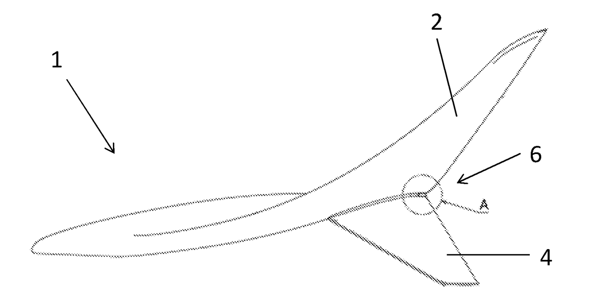
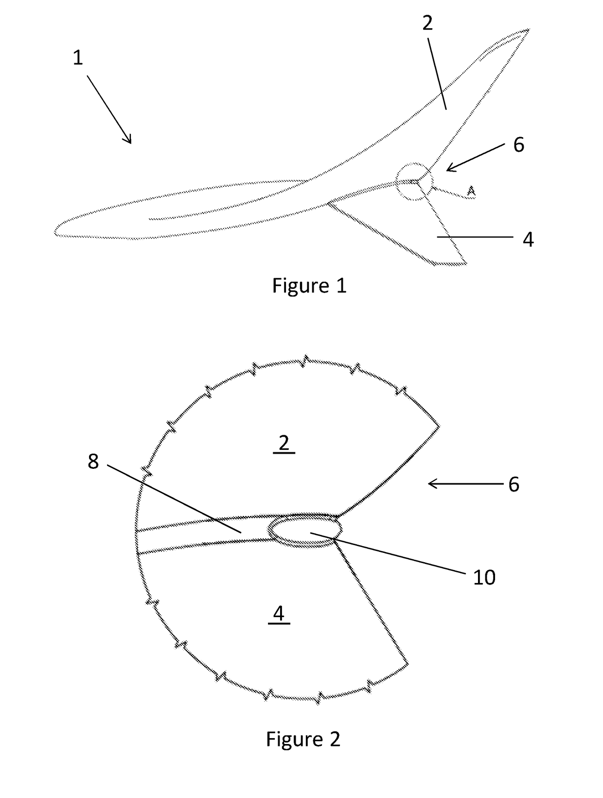
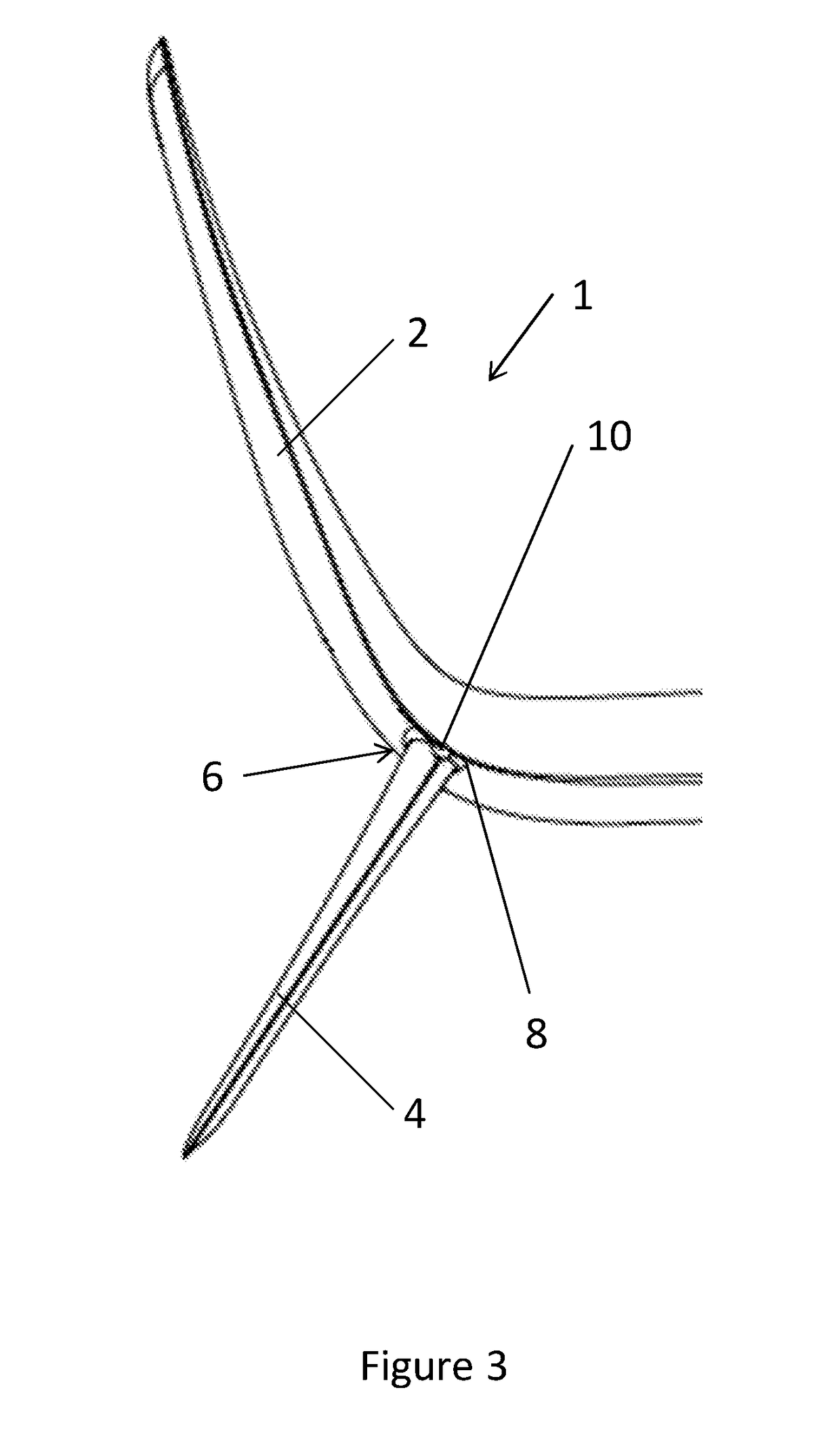
[0036]FIG. 3 shows a rear view of the wingtip device 1 of the As shown in FIG. 3 the light 10 is located on the mean camber line of the downwardly extending winglet 4, at the point which is closest to the mean camber line of the upwardly extending winglet. The angle between the upwardly extending winglet 2 and downwardly extending winglet 4 is around 130 degrees. The angle between the wing plane and the tip of the upwardly extending winglet 2 is around 120 degrees, and the angle between the wing plane and the downwardly extending winglet 4 is around 120 degrees.

[0037]As can be seen from FIGS. 1 to 3, wingtip devices in accordance with the present embodiment may experience less drag as locating the light 10 at the join 6 allows the majority of the body of the light 10 to sit within the join thereby shielding it from the airflow around the wingtip device when the aircraft is in flight. Positioning the obstruction light 10 at the trailing edge of the wingtip device 1 may also allow fo...

second embodiment

[0040]Whilst the present invention has been described and illustrated with reference to particular embodiments, it will be appreciated by those of ordinary skill in the art that the invention lends itself to many different variations not specifically illustrated herein. By way of example only, certain possible variations will now be described. The second embodiment described above uses brackets to fix the downwardly extending winglet to the upwardly extending winglet, it will be appreciated that any type of fixings may be used with the present invention. It will also be appreciated that the type of light used with the present invention may vary, as well as its position along the length of the join. For example, in some embodiments in accordance with the present invention the light may be located adjacent to the leading edge of the downwardly extending winglet.


PUM


Abstract

A wingtip device 1 including an upwardly extending winglet 2 and a downwardly extending winglet 4. The downwardly extending winglet 4 is connected to the upwardly extending winglet 2 at a join 6. An aircraft light 10 is located at the join 6 between the upwardly extending winglet 2 and the downwardly extending winglet 4.

Description

BACKGROUND OF THE INVENTION[0001]The present invention concerns aircraft lights. More particularly, but not exclusively, this invention concerns the inclusion of an aircraft light in a wingtip device and an aircraft including such a wingtip device. The invention also concerns a method of integrating an aircraft light with a wingtip device.[0002]Aircraft may include a number of lights for navigation purposes, or to illuminate various elements of the aircraft and / or its surroundings. Depending on the purpose of the light there may be a need to position a light within certain regions of the aircraft. For example, rear-facing wing lights would typically need to be located near the trailing edge of the wing in order that the light cone produced by such a light can extend rearwards without being obstructed by the aircraft structure.[0003]Drag reduction is a key element of the increased efficiency achieved by modern aircraft. It is therefore desirable that the additional drag generated by ...

Claims


Application Information

Patent Timeline
Patent Type & Authority Applications(United States)
IPC IPC(8): B64D47/02B64D47/04B64C23/06
CPCB64D47/02B64D47/04B64C23/069B64D47/06B64D2203/00Y02T50/10
Inventor MEISNER, ANTHONY
Owner AIRBUS OPERATIONS LTD
Why Eureka
Try Eureka