Characteristic determining apparatus and control device using same

a technology of characteristic determining device and control device, which is applied in the direction of electric control, instruments, machines/engines, etc., can solve the problems of increasing the manufacturing cost of the characteristic determining device, the complicated layout of the lead wire extending from the pressure sensor, and the decrease of so as to reduce the manufacturing cost of the characteristic determining device, the structure is simplified, and the manufacturing cost is reduced.

Active Publication Date: 2018-01-11
DENSO CORP
View PDF20 Cites 6 Cited by
  • Summary
  • Abstract
  • Description
  • Claims
  • Application Information

AI Technical Summary

Benefits of technology

The patent describes a device that uses a single pressure sensor to measure pressure in multiple fuel injectors, which simplifies the structure and reduces manufacturing costs compared to using multiple sensors for each injector. The device may also have a second pressure sensor to measure pressure in the delivery pipe, which increases accuracy and enables a wider range of pressure measurement.

Problems solved by technology

The characteristics determining device, as described above, uses the plurality of pressure sensors in measuring the pressure of fuel in the respective fuel injectors, thus resulting in complicated layout of lead wires extending from the pressure sensors.
The pressure sensors are designed to output a signal indicating absolute values of pressure in the fuel injectors, thereby resulting in an increase in manufacturing cost of the characteristic determining device.
The first pressure sensor needs not measure an absolute value of pressure in each of the fuel injectors, thereby enabling the first pressure sensor to be designed to have a relatively narrow measurable range, which leads to a decrease in manufacturing cost of the characteristic determining device.

Method used


Image

  • Characteristic determining apparatus and control device using same
  • Characteristic determining apparatus and control device using same
  • Characteristic determining apparatus and control device using same

Examples


first embodiment

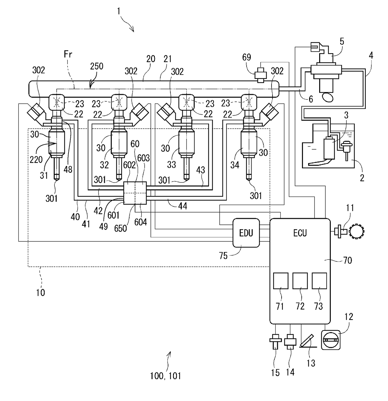
[0024]The fuel injection system 1 is equipped with a characteristic determiner and control device according to the first embodiment.

[0025]Specifically, the fuel injection system 1 is installed in a vehicle such as an automobile, not shown. The fuel injection system 1 is engineered to control spraying or injecting of fuel or gasoline into the engine 10 (i.e., an internal combustion engine) mounted in the vehicle. The engine 10 is, for example, an in-line four-cylinder gasoline engine.

[0026]The fuel injection system 1 is, as illustrated in FIG. 1, equipped with the fuel tank 2, the fuel pump 3, the pipe 4, the high-pressure pump 5, the pipe 6, the delivery pipe 20, the fuel injectors 30, the characteristic determining device 100, and the control device 101.

[0027]The fuel tank 2 stores gasoline (i.e., fuel) therein. The fuel pump 3 is installed in the fuel tank 2 and works to suck fuel from the fuel tank 2 and deliver it to the high-pressure pump 5 through the pipe 4. The high-pressure...

second embodiment

[0089]FIG. 3 illustrates the fuel injection system 1 equipped with the characteristic determining device 100 and the control device 101 according to the second embodiment. The pipes 40 and the first pressure sensor 60 are different in structure from those in the first embodiment. Specifically, the characteristic determining device 100 is equipped with two first pressure sensor 60 which will also be denoted by numerals 61 and 62 for the sake of ease of explanation.

[0090]The first pressure sensor 61, as illustrated in FIG. 4, has the second ends 49 of the pipes 41 and 42 joined thereto. The first pressure sensor 61 has formed therein two inner chambers which are isolated from each other and define the input ports 600 to which the pipes 40 (41 and 42) lead, respectively. The pipes 41 and 42, thus, do not communicate with each other, so that fuel does not flow one of the pipes 41 and 42 to the other. Each of the pipes 40 is fully filled with fuel when the characteristic determining devi...

third embodiment

[0125]FIG. 7 illustrates the fuel injection system 1 equipped with the characteristic determining device 100 and the control device 101 according to the third embodiment. This embodiment is different in how to connect between the pipes 40 and the first pressure sensors 60 from the second embodiment.

[0126]The pipe 43 is joined at the second end 49 to the input port 602 of the first pressure sensor 61, so that the internal injector pressure that is the pressure of fuel in the fuel injector 33 is inputted to the input port 602 of the first pressure sensor 61 through the pipe 43.

[0127]The pipe 42 is joined at the second end 49 to the input port 601 of the first pressure sensor 62, so that the internal injector pressure that is the pressure of fuel in the fuel injector 32 is inputted to the input port 601 of the first pressure sensor 62 through the pipe 42.

[0128]Other arrangements of the third embodiment are identical with those of the second embodiment, and explanation thereof in detail...


PUM


Abstract

A characteristic determining device is provided which determines fuel injection characteristics of a plurality of fuel injectors for an internal combustion engine. The characteristic determining device includes a pressure sensor and a plurality of pipes each of which connects between the pressure sensor and one of the fuel injectors. The pressure sensor is designed to have a plurality of pressure inputs from the respective fuel injectors through the pipes and outputs a signal indicative of a level of pressure in each of the fuel injectors. The characteristic determining device analyzes the signals from the first pressure sensor to determine the fuel injection characteristics of the respective fuel injectors. These arrangements result in a simplified structure of the characteristic determining device and a decreased manufacturing cost thereof.

Description

CROSS REFERENCE TO RELATED DOCUMENT[0001]The present application claims the benefit of priority of Japanese Patent Application No. 2016-134714 filed on Jul. 7, 2016, the disclosure of which is incorporated herein by reference.BACKGROUND1 Technical Field[0002]The invention relates generally to a characteristic determining apparatus working to determine fuel injection characteristic of fuel injectors which may be employed in internal combustion engines for automobiles.2 Background Art[0003]Japanese Patent First Publication No. 2009-57924 teaches a characteristic determining device working to determine fuel injection characteristics of fuel injectors which spray fuel into an internal combustion engine. The characteristic determining device is equipped with a plurality of pressure sensors which are mounted in a delivery pipe one for each of the fuel injectors. Each of the pressure sensors measures a pressure level in one of the fuel injectors when being opened to spry the fuel. The char...

Claims


Application Information

Patent Timeline
Patent Type & Authority Applications(United States)
IPC IPC(8): F02M65/00F02M55/00F02D41/30F02M63/00F02M57/00
CPCF02M65/00F02M57/005F02D2200/0602F02M63/0031F02D41/3005F02M55/008F02M55/00F02D41/40F02D2200/0616F02D2200/0618F02D2400/08F02M2200/247Y02T10/40F02M65/001F02M65/003
Inventor FURUKAWA, TAKASHI
Owner DENSO CORP
Why Eureka
Try Eureka