
CHARACTERIZATION OF PHASE SHIFTER CIRCUITRY IN INTEGRATED CIRCUITS (ICs) USING STANDARD AUTOMATED TEST EQUIPMENT (ATE)

a phase shifter and integrated circuit technology, applied in the direction of electronic circuit testing, measurement devices, instruments, etc., can solve the problems of capital intensive and early approaches to measuring phase shift in production, and achieve the effect of reducing the complexity of testing, confirming the functionality and performance of the dut, and being easy to understand

Active Publication Date: 2018-01-11
ADVANTEST CORP
View PDF4 Cites 4 Cited by
  • Summary
  • Abstract
  • Description
  • Claims
  • Application Information

AI Technical Summary

Benefits of technology

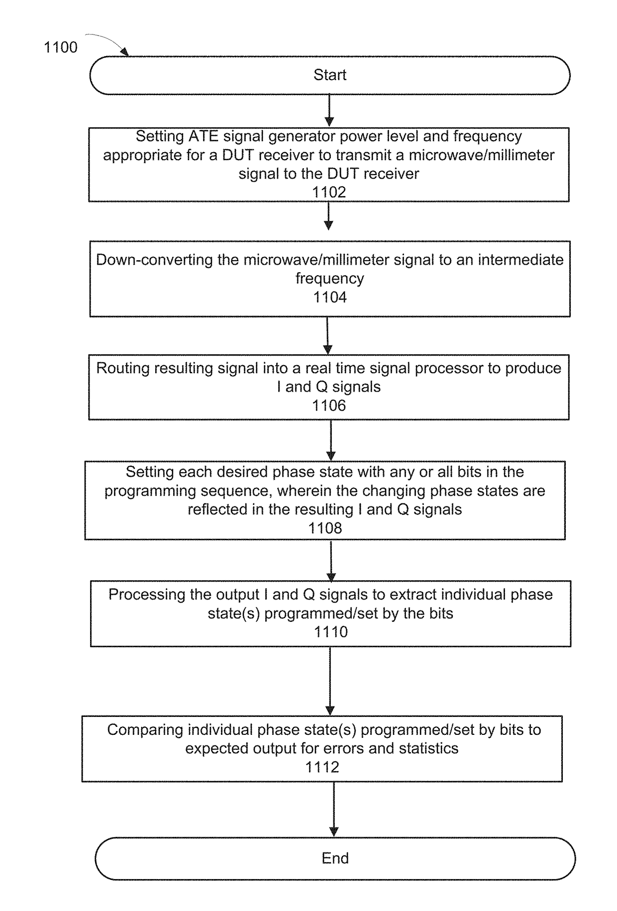
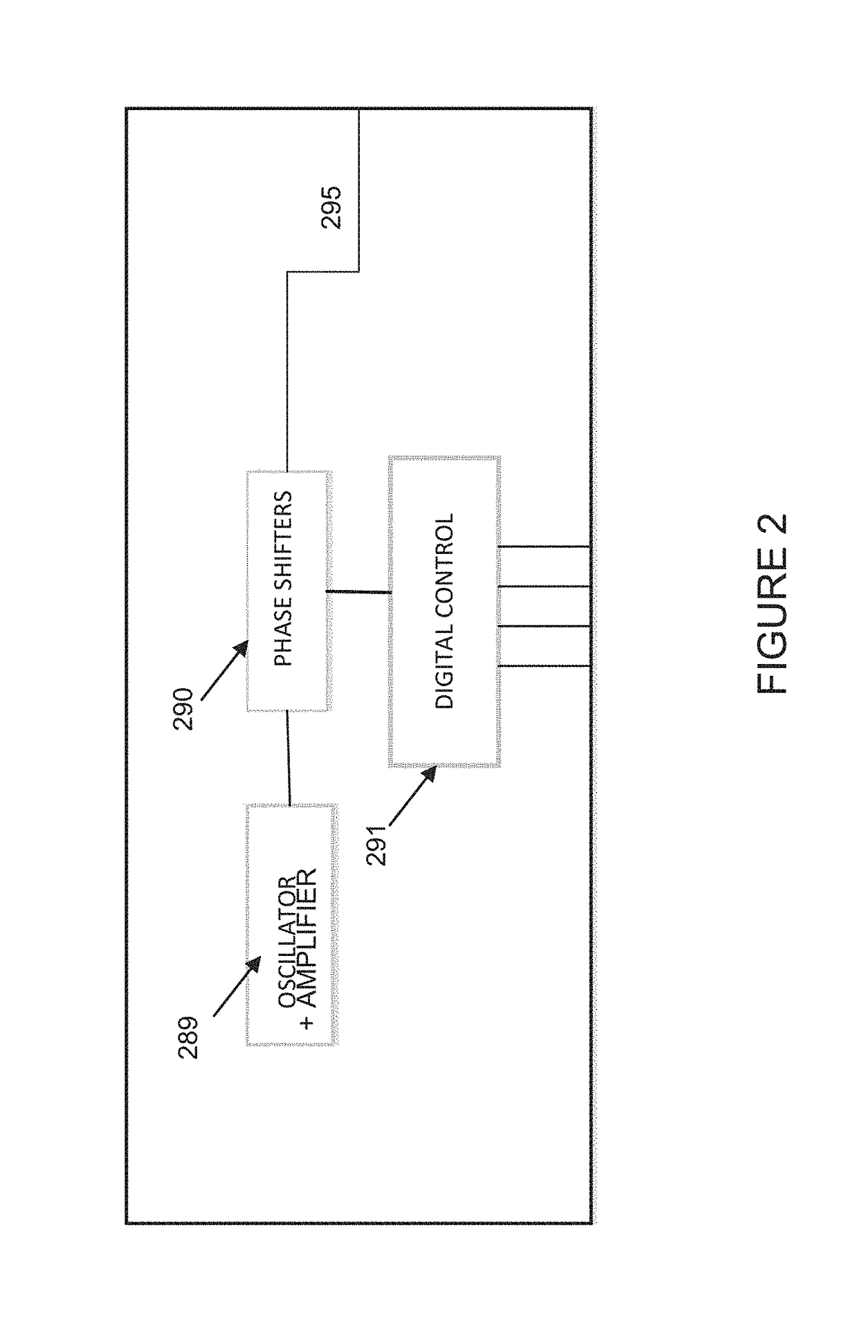
The present invention provides a method and apparatus for testing phase shifters. This method and apparatus reduce the complexity of testing phase shifters by providing several features. Firstly, it provides a visual indication of the manner in which the phase shifters are shifting states using time-domain plots. Secondly, it calculates metrics related to the actual performance of the phase shifts relative to the expected results, and determines the empirical results of the phase states and the distribution of results around each phase state. Lastly, it records the phase shift states to confirm the functionality and performance of the device. The method and apparatus allow for easier and more intuitive testing of phase shifters and can replicate external control using downloaded codes. This reduces the cost and complexity of testing and takes advantage of existing resources and computation power.

Problems solved by technology

As mentioned previously, earlier approaches for measuring the phase shift in production were quite difficult to implement, capital intensive, and typically could only be done on the laboratory bench.

Method used


Image

  • CHARACTERIZATION OF PHASE SHIFTER CIRCUITRY IN INTEGRATED CIRCUITS (ICs) USING STANDARD AUTOMATED TEST EQUIPMENT (ATE)
  • CHARACTERIZATION OF PHASE SHIFTER CIRCUITRY IN INTEGRATED CIRCUITS (ICs) USING STANDARD AUTOMATED TEST EQUIPMENT (ATE)
  • CHARACTERIZATION OF PHASE SHIFTER CIRCUITRY IN INTEGRATED CIRCUITS (ICs) USING STANDARD AUTOMATED TEST EQUIPMENT (ATE)

Examples


Embodiment Construction

[0029]Reference will now be made in detail to the various embodiments of the present disclosure, examples of which are illustrated in the accompanying drawings. While described in conjunction with these embodiments, it will be understood that they are not intended to limit the disclosure to these embodiments. On the contrary, the disclosure is intended to cover alternatives, modifications and equivalents, which may be included within the spirit and scope of the disclosure as defined by the appended claims. Furthermore, in the following detailed description of the present disclosure, numerous specific details are set forth in order to provide a thorough understanding of the present disclosure. However, it will be understood that the present disclosure may be practiced without these specific details. In other instances, well-known methods, procedures, components, and circuits have not been described in detail so as not to unnecessarily obscure aspects of the present disclosure.

[0030]E...


PUM


Abstract

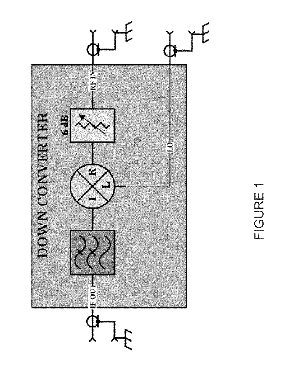
A method for characterizing a phase shifter in a device under test (DUT) using automated test equipment (ATE) is disclosed. The method comprises down converting an input signal received from the transmitter DUT to an intermediate frequency and routing the down converted input signal to a signal processor, wherein the signal processor generates I and Q signals using the input signal. The method further comprises setting an initial phase state on the phase shifter in the transmitter DUT and toggling at least one phase state bit to control the phase shifter to cycle through a plurality of phase states, wherein the changing phase states appear on the I and Q signals. Finally, the method comprises processing the I and Q signals to extract individual phase states programmed by the at least one phase state bit.

Description

FIELD OF THE INVENTION[0001]Embodiments of the present disclosure generally relate to Automatic Test Equipment (ATE) for testing electronic components.BACKGROUND[0002]Automatic Test Equipment (ATE) is commonly used within the field of electronic chip manufacturing for the purposes of testing electronic components. ATE systems both reduce the amount of time spent on testing devices to ensure that the device functions as designed and serve as a diagnostic tool to determine the presence of faulty components within a given device before it reaches the consumer.[0003]In general, components, for example, electronic components or devices, micro-electronic chips, memory chips or other integrated circuits (IC), are usually tested before they are delivered to a customer. Testing may be performed in order to prove and ensure the correct functional capability of the devices. The tests are usually performed by means of an automated test equipment or test system. Examples for such ATE are the Adv...

Claims


Application Information

Patent Timeline
Patent Type & Authority Applications(United States)
IPC IPC(8): G01S7/40G01S13/931
CPCG01S7/4021G01S13/931G01S2013/0245G01S2013/0254G01R31/2834G01R31/2822
Inventor MCALEENAN, ROGER
Owner ADVANTEST CORP
Learn More