Finite element modeling of anatomical structure

a technology of finite element modeling and anatomical structure, applied in the field of generating a finite element model of anatomical structure, can solve the problems of complexity, error and/or lack of accuracy

Active Publication Date: 2018-01-11
KONINKLJIJKE PHILIPS NV
View PDF7 Cites 2 Cited by
  • Summary
  • Abstract
  • Description
  • Claims
  • Application Information

AI Technical Summary

Benefits of technology

[0006]It would be advantageous to obtain an improved system or method for generating a FE model of an anatomical structure with a desired mesh.
[0026]Based on the insight of the inventors, FE modeling may be based on a segmentation model, e.g., to indicate location and base shape of the anatomical structure in a medical image. FE modeling may then use the segmentation model as a starting point, e.g., as a base FE mesh, to suitably shape a pre-existing FE mesh, etc. A desired mesh property is frequently related to a particular anatomical region, in that the mesh property may be selected to reflect, e.g., a certain material type of the anatomical region. By associating the mesh property to a corresponding segmentation model part of the segmentation model, the FE modeling may directly, from the segmentation model and the therewith associated mesh property, generate the FE model with a finite element model part which corresponds with the pre-determined anatomical region of interest having the particular mesh property. It is therefore not needed for the user to specify the desired mesh property during the FE modeling as it is already associated with the segmentation model in the segmentation model. Compared to an automatic mesh generation based on mere geometric properties of the FE model, the system(s) enable anatomically specific knowledge to be used in the FE modeling. Aspects of the present invention may advantageously result in an efficient generation of the FE model with fewer iterations and alterations in the model or in the mesh in order to generate an optimal meshing of the FE model. Furthermore, mistakes by the user when altering / correcting the mesh / model may be minimized. In addition, user tendency to use too-fine mesh in order to ‘stay on the safe side’ may be avoided.
[0027]Optionally, the mesh property is selected based on at least one out of: (i) a material type of the pre-determined anatomical region of interest (ii) a medical and / or biological condition at the pre-determined anatomical region of interest (iii) a mechanical boundary condition at the pre-determined anatomical region of interest (iv) an anatomical shape of the pre-determined anatomical region of interest. For example, when modeling a cavity, a higher mesh resolution may be used at the wall for computational fluid dynamic (CFD) simulations. In another example, in fluid-solid interaction (FSI) simulations, used, e.g., for blood flow simulations in a cavity, solid part and fluid part may share vertices and mesh topology at the solid-fluid boundary. Such selection of the mesh property based on different simulation conditions may advantageously allow taking various prior knowledge / information into account when generating the finite element model.

Problems solved by technology

Here, the complexity may stem, for example, from complex geometrical characteristics or boundary conditions.
In addition, the user may often be required to manually assess the requirements for obtaining a desired mesh in the FE models, which may be prone to mistake and / or lack of accuracy.

Method used


Image

  • Finite element modeling of anatomical structure
  • Finite element modeling of anatomical structure
  • Finite element modeling of anatomical structure

Examples


Embodiment Construction

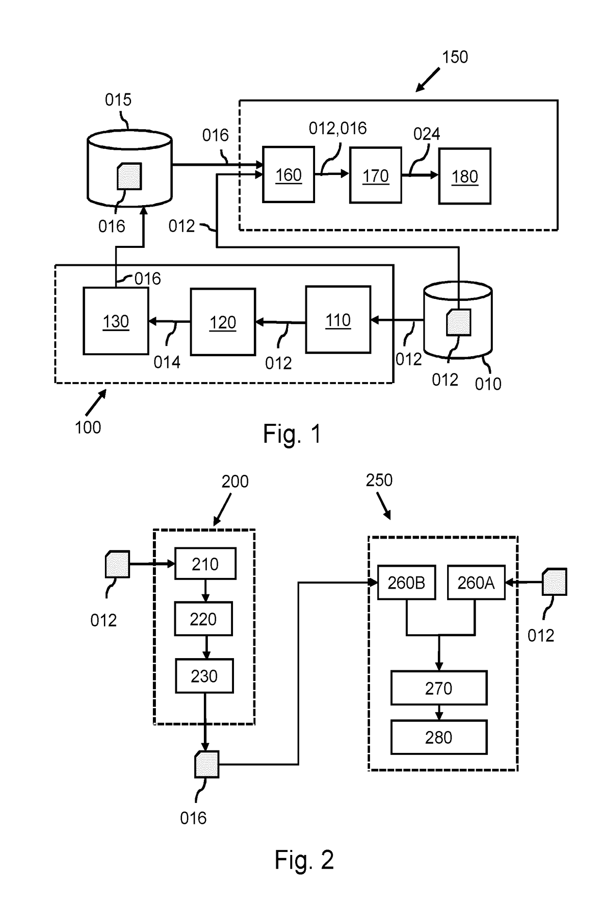
[0058]FIG. 1 shows a first system 100 for generating association data for use in generating the finite element model of an anatomical structure. FIG. 1 further shows a second system 150 for generating a finite element model of the anatomical structure based on a fitted model of the anatomical structure and association data.

[0059]The first system 100 may comprise an input interface 110 configured for obtaining model data 012 defining a segmentation model for segmenting the anatomical structure, the segmentation model representing a reference shape of the anatomical structure. The model data may be obtained for example, from a database 010.

[0060]The first system 100 may further comprise an identifying subsystem 120 configured for identifying a pre-determined anatomical region of interest in the segmentation model, the pre-determined anatomical region of interest having been pre-determined based on a mesh property being desired in meshing a finite element model part of the finite eleme...


PUM


Abstract

A system and method is provided for generating a finite element (FE) model of an anatomical structure based on a fitted model (340) of the anatomical structure and association data. A segmentation model (310) may be provided for segmenting the anatomical structure. Association data may be obtained which associates a segmentation model part (315) of the segmentation model (310) with a mesh property, the segmentation model part (315) representing a pre-determined anatomical region of interest. The segmentation model may be applied to a medical image (320) of a subject, thereby obtaining a fitted model (340) providing a segmentation of the anatomical structure (330). The finite element model (350) may then be generated based on the fitted model (340) and the association data, said generating comprising meshing a finite element model part of the finite element model in accordance with the mesh property, the finite element model part corresponding with the pre-determined anatomical region of interest. Advantageously, this may result in an efficient generation of the FE model needing fewer manual iterations and / or alterations in the model or in the mesh.

Description

FIELD OF THE INVENTION[0001]The invention relates to a system and a method for generating a finite element model of an anatomical structure. The invention further relates to a system and a method for generating association data for use in generating the finite element model of the anatomical structure. The invention further relates to association data for use in generating the finite element model. The invention further relates to a workstation and imaging apparatus comprising the respective system, and to a computer program product comprising instructions for causing processor systems to perform the respective method.BACKGROUND OF THE INVENTION[0002]Finite Element (FE) methods are numerical methods for approximating solutions of mathematical differential equations governing a domain such as structure. For example, the differential equations may describe a physical or chemical phenomenon in the structure. FE modeling, which is modeling of a structure based on FE methods, may be used...

Claims


Application Information

Patent Timeline
Patent Type & Authority Applications(United States)
IPC IPC(8): G06T17/20A61B5/00
CPCG06T17/20G06T7/149A61B2576/023A61B5/7425G06T2210/41G06F30/23
Inventor NOLAN, JULIAN CHARLESLAWRENSON, MATTHEW JOHNWEESE, JUERGEN
Owner KONINKLJIJKE PHILIPS NV
Why Eureka
Try Eureka