Band pass filter and laminate band pass filter

a band pass filter and laminate technology, applied in the direction of fixed inductances, inductances, electrical devices, etc., can solve the problems of band pass filter characteristics deviating from the desired range, difficult adjustment of magnetic couplings, and weak strength of magnetic couplings, etc., to achieve easy adjustment and easy adjustment

Active Publication Date: 2018-01-11
MURATA MFG CO LTD
View PDF3 Cites 6 Cited by
  • Summary
  • Abstract
  • Description
  • Claims
  • Application Information

AI Technical Summary

Benefits of technology

[0053]Furthermore, when the multilayer body is seen in the laminate direction, the winding direction of the spiral electrode of the first inductor of the at least one LC parallel resonator or at least one of the LC parallel resonators at the intermediate stage may be coincident with the winding direction of the spiral electrode of the inductor of the one of the adjacent LC parallel resonators in the equivalent circuit, and, in addition, the winding direction of the spiral electrode of the second inductor of the at least one LC parallel resonator or the at least one of the LC parallel resonators at the intermediate stage may be opposite to the winding direction of the spiral electrode of the inductor of the other adjacent LC parallel resonator in the equivalent circuit. Alternatively, the winding direction of the spiral electrode of the first inductor of the at least one LC parallel resonator or the at least one of the LC parallel resonators at the intermediate stage may be opposite to the winding direction of the spiral electrode of the inductor of the one of the adjacent LC parallel resonators in the equivalent circuit, and, in addition, the winding direction of the spiral electrode of the second inductor of the at least one LC parallel resonator or the at least one of the LC parallel resonators at the intermediate stage may be coincident with the winding direction of the spiral electrode of the inductor of the other adjacent LC parallel resonator in the equivalent circuit. In this case, one of the strengths of the following magnetic couplings is able to be increased and the other of the following strengths of the magnetic couplings is able to be decreased: the magnetic coupling between the first inductor of the at least one LC parallel resonator or the at least one of the LC parallel resonators at the intermediate stage and the inductor of the one of the adjacent LC parallel resonators in the equivalent circuit; and the magnetic coupling between the second inductor of the at least one LC parallel resonator or the at least one of the LC parallel resonators at the intermediate stage and the inductor of the other adjacent LC parallel resonator in the equivalent circuit.
[0054]In band pass filters according to preferred embodiments of the present invention, the inductor of the at least one LC parallel resonator at the intermediate stage is divided into the first inductor and the second inductor connected in parallel with each other. In addition, the first inductor is magnetically coupled to the inductor of the one of the adjacent LC parallel resonators, and the second inductor is magnetically coupled to the inductor of the other adjacent LC parallel resonator. Thus, the strength of the magnetic coupling between the first inductor and the inductor of the one of the adjacent LC parallel resonators and the strength of the magnetic coupling between the second inductor and the inductor of the other adjacent LC parallel resonator are able to be easily adjusted. For example, both the strengths are able to be easily equalized.
[0055]Furthermore, laminate band pass filters according to preferred embodiments of the present invention include multilayer bodies in which insulating layers are laminated. Thus, the strength of the magnetic coupling between the first inductor and the inductor of the one of the adjacent LC parallel resonators and the strength of the magnetic coupling between the second inductor and the inductor of the other adjacent LC parallel resonator are able to be easily adjusted. For example, both the strengths are able to be easily equalized. Furthermore, in laminate band pass filters according to preferred embodiments of the present invention, when the multilayer body is seen in the laminate direction, the spiral electrode of the first inductor of the at least one LC parallel resonator or the at least one of the LC parallel resonators at the intermediate stage is superposed on the spiral electrode of the inductor of the one of the adjacent LC parallel resonators in the equivalent circuit, and the spiral electrode of the second inductor of the at least one LC parallel resonator or the at least one of the LC parallel resonators at the intermediate stage is superposed on the spiral electrode of the inductor of the other adjacent LC parallel resonator in the equivalent circuit. Thus, the strength of the magnetic coupling between the first inductor of the at least one LC parallel resonator or the at least one of the LC parallel resonators at the intermediate stage and the inductor of the one of the adjacent LC parallel resonators in the equivalent circuit is increased, and the strength of the magnetic coupling between the second inductor of the at least one LC parallel resonator or the at least one of the LC parallel resonators at the intermediate stage and the inductor of the other adjacent LC parallel resonator in the equivalent circuit is increased.

Problems solved by technology

Furthermore, in the band pass filter 500, there is a significant problem in that the strength of the magnetic coupling M1 between the inductor L1 and the inductor L2 and the strength of the magnetic coupling M2 between the inductor L2 and the inductor L3 are slightly different from each other instead of being completely matched to each other.
Thus, the adjustment of the magnetic coupling is not an easy task.
Thus, even when magnetic coupling between the inductors of the LC parallel resonators can be adjusted, another problem such as the filter characteristic of the band pass filter deviating from a desired range may arise.

Method used


Image

  • Band pass filter and laminate band pass filter
  • Band pass filter and laminate band pass filter
  • Band pass filter and laminate band pass filter

Examples


first preferred embodiment

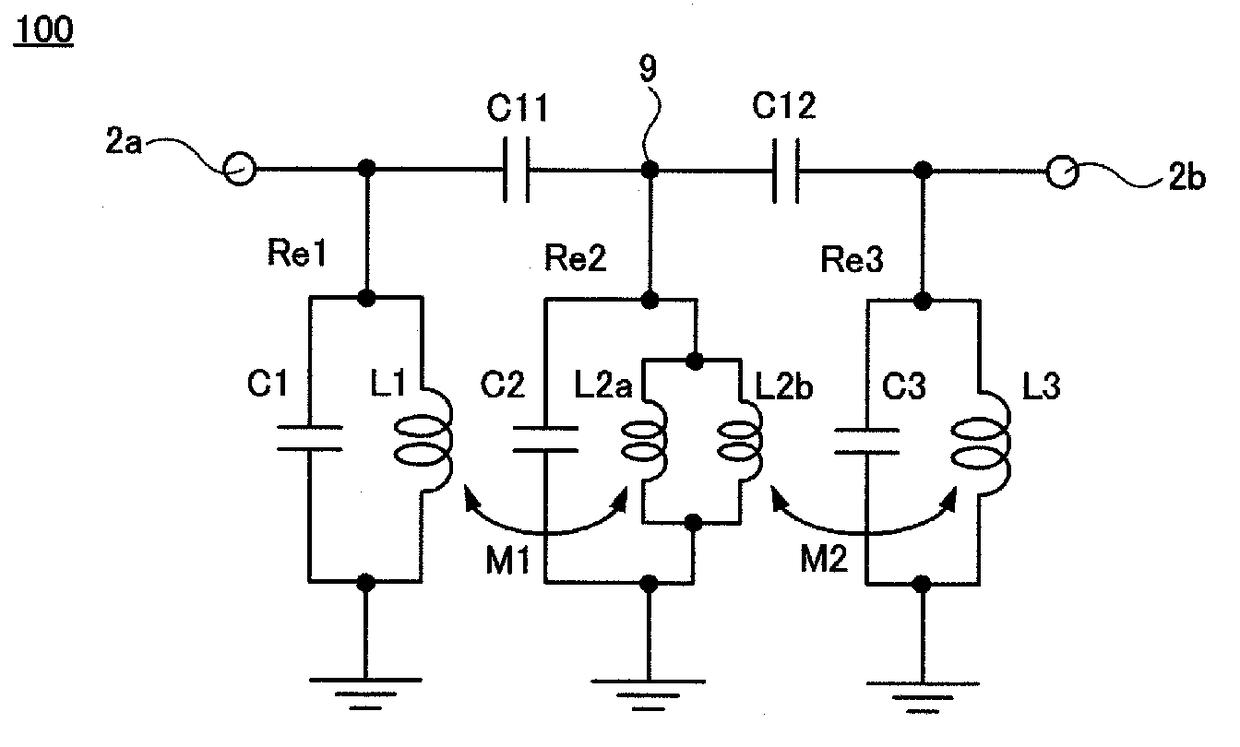
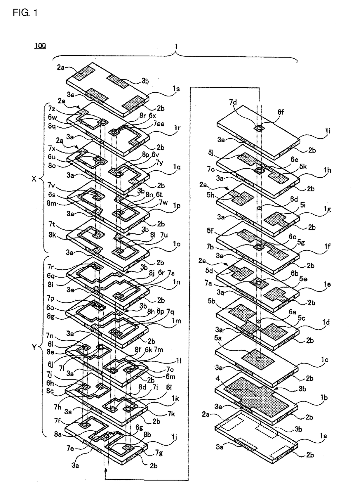
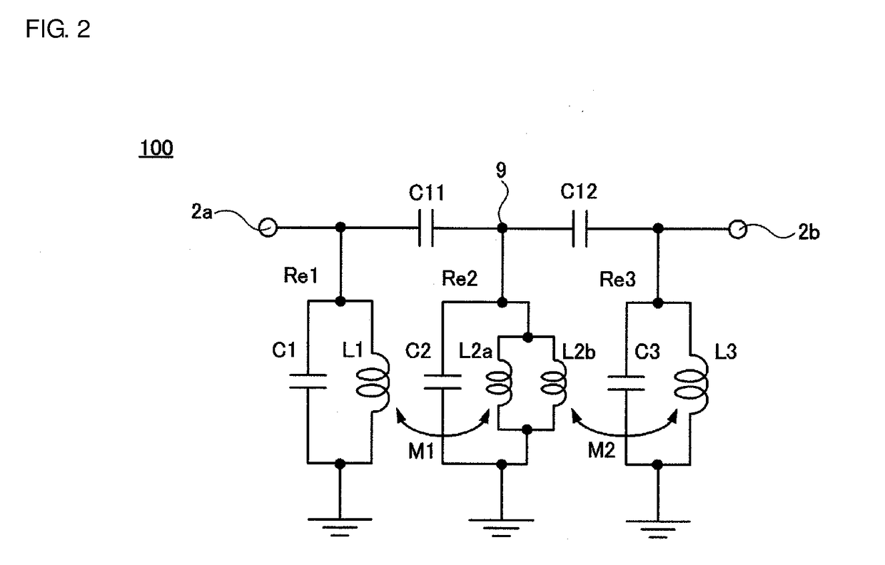
[0072]FIGS. 1 and 2 illustrate a band pass filter 100 according to a first preferred embodiment of the present invention. In more detail, FIG. 1 is an exploded perspective view of the band pass filter 100 when the band pass filter 100 includes a multilayer body in which laminate insulating layers are laminated. FIG. 2 is a diagram in which the configuration of the exploded perspective view illustrated in FIG. 1 is replaced with an equivalent circuit.

[0073]As illustrated in FIG. 1, the band pass filter 100 includes a multilayer body 1 in which 19 insulating layers 1a to is are sequentially laminated from the bottom. The multilayer body 1 preferably has a rectangular or substantially rectangular parallelepiped shape.

[0074]The insulating layers 1a to 1s are preferably made of ceramic. Each of the insulating layers 1a to 1s can also be a dielectric layer having a dielectric constant.

[0075]The insulating layer 1a having a rectangular or substantially rectangular shape includes four side ...

second preferred embodiment

[0150]FIG. 8 is a band pass filter 200 according to a second preferred embodiment of the present invention. FIG. 8 is an equivalent circuit diagram of the band pass filter 200.

[0151]The band pass filter 200 includes a first input / output terminal 2a and a second input / output terminal 2b.

[0152]Three capacitive coupling capacitors C11, C12, and C13 are connected between the first input / output terminal 2a and the second input / output terminal 2b.

[0153]The band pass filter 200 includes an LC parallel resonator Re1 at a first input / output stage, two LC parallel resonators Re2 and Re3 at an intermediate stage, and an LC parallel resonator Re4 at a second input / output stage. The number of LC parallel resonators at the intermediate stage is larger in the band pass filter 200 than in the band pass filter 100 according to the first preferred embodiment having been described. Accordingly, the pass band is widened and attenuation is increased.

[0154]The LC parallel resonator Re1 at the first inp...

third preferred embodiment

[0163]FIG. 9 is a band pass filter 300 according to a third preferred embodiment of the present invention. FIG. 9 is an equivalent circuit diagram of the band pass filter 300.

[0164]The band pass filter 300 includes a first input / output terminal 2a and a second input / output terminal 2b.

[0165]Four capacitive coupling capacitors C11, C12, C13, and C14 are connected between the first input / output terminal 2a and the second input / output terminal 2b.

[0166]The band pass filter 300 includes an LC parallel resonator Re1 at a first input / output stage, three LC parallel resonators Re2, Re3, and Re4 at an intermediate stage, and an LC parallel resonator Re5 at a second input / output stage. The number of LC parallel resonators at the intermediate stage is larger in the band pass filter 200 than in the band pass filter 100 according to the first preferred embodiment and the band pass filter 200 according to the second preferred embodiment having been described. Accordingly, the pass band is wide...


PUM


Abstract

A band pass filter includes parallel resonators. An inductor of a first parallel resonator at an intermediate stage is divided into a first inductor and a second inductor connected in parallel with each other. The first inductor and an inductor of a second parallel resonator are in magnetic coupling with each other, and the second inductor and an inductor of a third parallel resonator are in magnetic coupling with each other.

Description

CROSS REFERENCE TO RELATED APPLICATIONS[0001]This application claims the benefit of priority to Japanese Patent Application No. 2015-060087 filed on Mar. 23, 2015 and is a Continuation Application of PCT Application No. PCT / JP2016 / 051337 filed on Jan. 18, 2016. The entire contents of each application are hereby incorporated herein by reference.BACKGROUND OF THE INVENTION1. Field of the Invention[0002]The present invention relates to a band pass filter. More particularly, the present invention relates to a band pass filter in which magnetic coupling between inductors of adjacent LC parallel resonators is easily adjusted.[0003]Furthermore, the present invention relates to a laminate band pass filter in which the above-described band pass filter includes a multilayer body in which insulating layers are laminated one on top of another. More particularly, the present invention relates to a laminate band pass filter in which magnetic coupling between the inductors of the adjacent LC paral...

Claims


Application Information

Patent Timeline
Patent Type & Authority Applications(United States)
IPC IPC(8): H03H7/09H03H7/075H03H7/01
CPCH03H7/09H03H7/075H03H7/0161H01F17/0013H01F2017/0026H03H7/0115H03H7/1775H03H2001/0085
Inventor ASADA, SATOSHI
Owner MURATA MFG CO LTD
Why Eureka
Try Eureka