Welding device and welding method

a welding device and welding method technology, applied in welding/cutting media/materials, welding apparatus, manufacturing tools, etc., can solve the problems of hydrogen cracking, hydrogen embrittlement of weld metal, hydrogen cracking of weld metal due to diffusible hydrogen (hydrogen atoms h) in weld metal, etc., to reduce the amount of diffusible hydrogen in weld metal

Active Publication Date: 2018-01-18
KOBE STEEL LTD
View PDF9 Cites 4 Cited by
  • Summary
  • Abstract
  • Description
  • Claims
  • Application Information

AI Technical Summary

Benefits of technology

[0018]According to the present invention, it is possible to reduce an amount of diffusible hydrogen in weld metal.

Problems solved by technology

In welding industry, hydrogen embrittlement and hydrogen cracking of the weld metal due to diffusible hydrogen (hydrogen atoms H) in the weld metal become problem.
The diffusible hydrogen in the weld metal collects in a minute space or a grain boundary of a steel structure to become hydrogen molecules (H2), and the volume expands, and this expansion pressure causes cracking, which results in destruction of a structure.

Method used


Image

  • Welding device and welding method
  • Welding device and welding method
  • Welding device and welding method

Examples


example

[0111]Now, an experimental result is illustrated, and an example of this embodiment will be described.

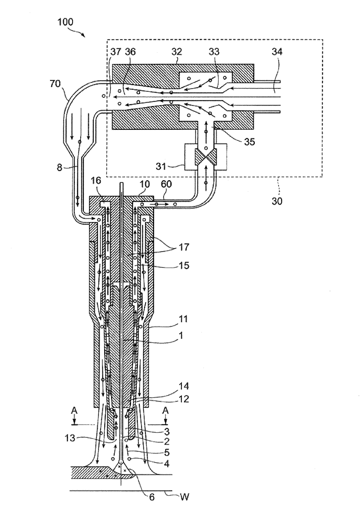
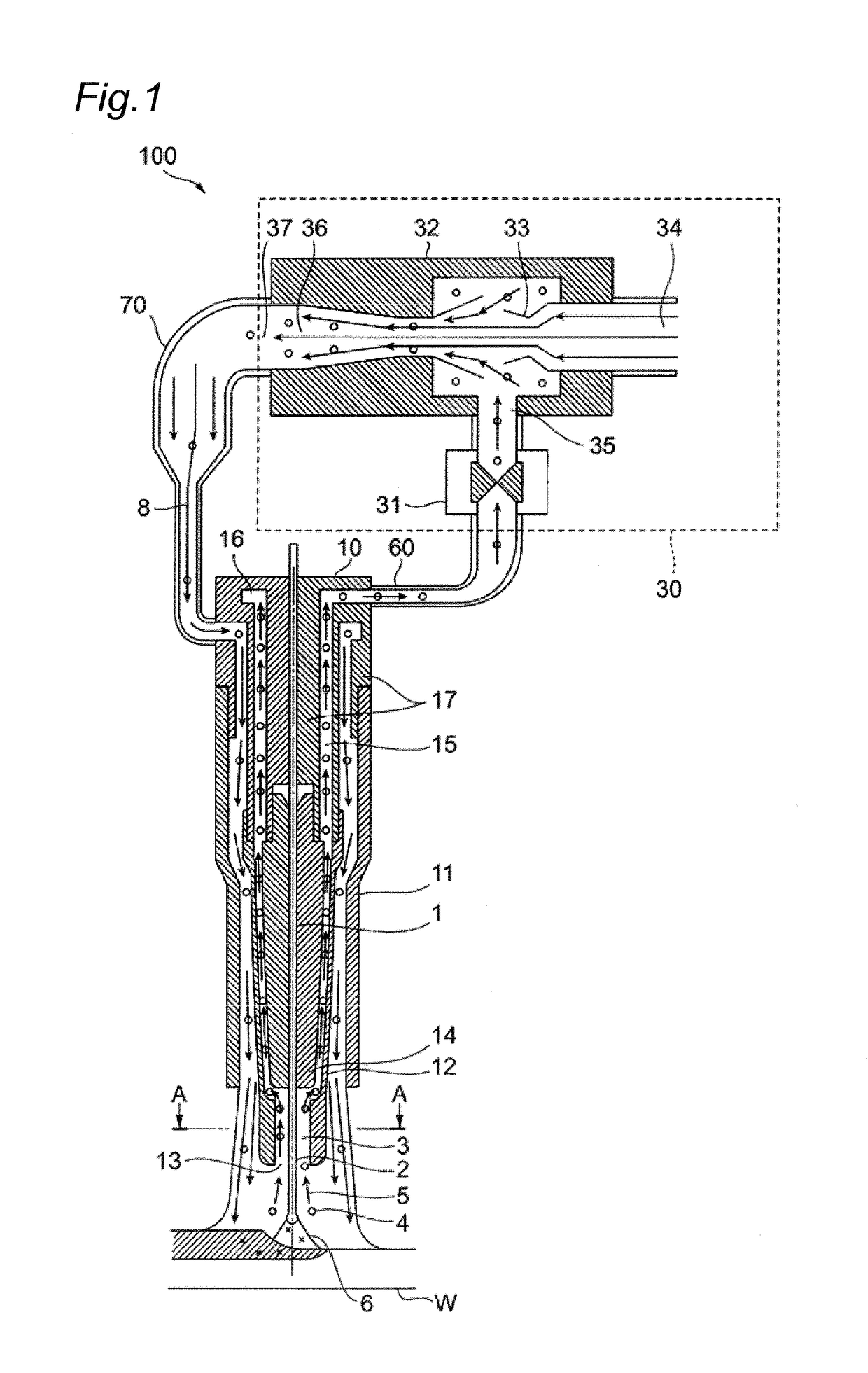
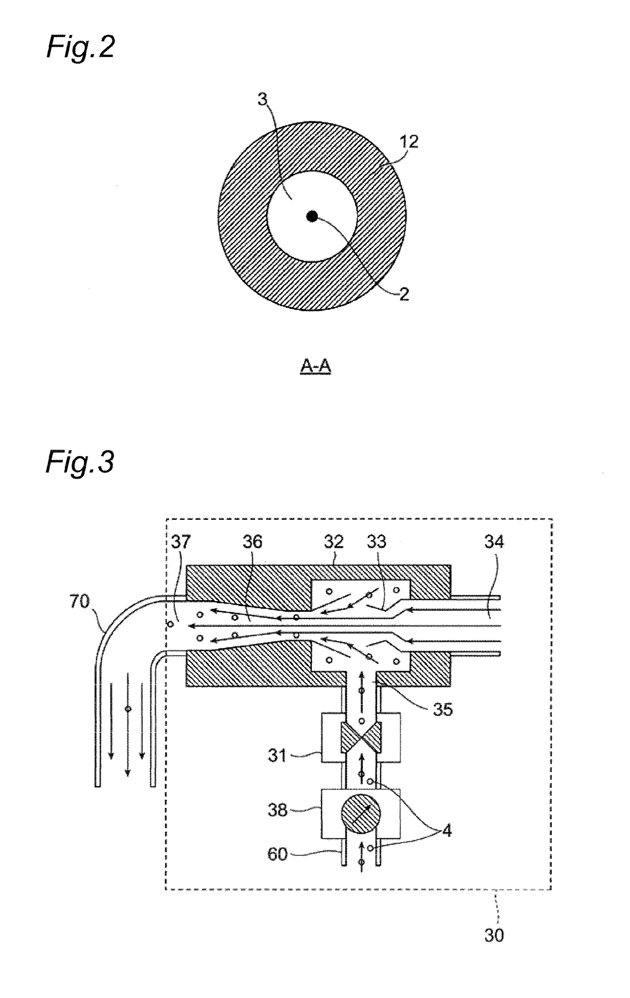
[0112]In the welding system 100 illustrated in FIG. 1, under a welding condition that a flow rate of shielding gas supplied from the shielding gas supply nozzle 11 was 25 liters / min, the wire protruding length was 25 mm, and a welding current was 270 amperes (unit of current: A), welding was performed by use of a flux cored wire which did not contain fluoride and had a diameter of 1.2 mm. A diffusible hydrogen amount in weld metal in a case where suction was not performed by the suction device 30, and a diffusible hydrogen amount in weld metal in a case where suction was performed by the suction device 30 were measured. Additionally, in the case where the suction was performed by the suction device 30, a suction flow rate of shielding gas sucked from the vicinity of the wire protruding section 2 by the suction nozzle 12 was set to 5 liters / min, and the sucked shielding gas was mixed...


PUM

PropertyMeasurementUnit
temperatureaaaaaaaaaa
diameteraaaaaaaaaa

Abstract

A welding system includes a welding torch that welds a workpiece by using a wire, a suction device that sucks shielding gas, and a sucked shielding gas supply path for allowing the sucked shielding gas to flow, wherein the welding torch includes a contact chip that guides the wire, a shielding gas supply nozzle that supplies the shielding gas to a weld zone, and a suction nozzle that surrounds a periphery of the wire protruding from the contact chip, and is opened toward a tip of the wire to suck the shielding gas.

Description

TECHNICAL FIELD[0001]The present invention relates to a welding device and a welding method.BACKGROUND ART[0002]In welding industry, hydrogen embrittlement and hydrogen cracking of the weld metal due to diffusible hydrogen (hydrogen atoms H) in the weld metal become problem. The diffusible hydrogen in the weld metal collects in a minute space or a grain boundary of a steel structure to become hydrogen molecules (H2), and the volume expands, and this expansion pressure causes cracking, which results in destruction of a structure. In such hydrogen cracking, while hydrogen cracking sensitivity is enhanced as the strength of steel is increased, high tensile steel having high strength recently tends to be used in welding.[0003]FIG. 20 is a diagram for illustrating a process of absorbing diffusible hydrogen in weld metal. FIG. 20 illustrates a wire, assuming that a flux cored wire (FCW (Flux Cored Wire)) which is a wire containing flux is used as the wire. FIG. 21 is a diagram illustratin...

Claims


Application Information

Patent Timeline
Patent Type & Authority Applications(United States)
IPC IPC(8): B23K9/173B23K9/29B23K9/32B23K35/36
CPCB23K9/173B23K9/295B23K9/32B23K35/36B23K35/30B23K9/324B23K35/3053B23K35/0266B23K9/16B23K9/29
Inventor KAWABE, NAOKIMARUYAMA, TOKUJIMIYATA, MINORUYAMAZAKI, KEISUZUKI, REIICHI
Owner KOBE STEEL LTD
Why Eureka
Try Eureka