Integrated modular electric power system for a vehicle

a technology of electric power system and integrated modules, which is applied in the direction of battery/fuel cell control arrangement, propulsion by capacitors, instruments, etc., can solve the problem of requiring additional power dissipation

Active Publication Date: 2018-01-18
HAMILTON SUNDSTRAND CORP
View PDF7 Cites 21 Cited by
  • Summary
  • Abstract
  • Description
  • Claims
  • Application Information

AI Technical Summary

Benefits of technology

[0004]In one exemplary embodiment a power system architecture for a vehicle includes a source management unit including at least a generator, a first stored energy component, and a second stored energy component, a high voltage DC bus connecting a high voltage load to the source management unit, at least one low voltage DC bus connecting at least one low voltage DC load to the source management unit, the source management unit including a plurality of multi-functional power modules configur

Problems solved by technology

Such systems, however, may require additional power dissipating r

Method used


Image

  • Integrated modular electric power system for a vehicle
  • Integrated modular electric power system for a vehicle
  • Integrated modular electric power system for a vehicle

Examples


Embodiment Construction

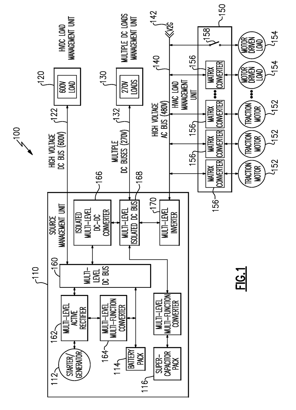
[0031]FIG. 1 schematically illustrates an exemplary electric power system 100 for utilization in a vehicle, such as a military vehicle. The electric power system 100 provides multiple levels of DC power to various loads 120, 130, as well as providing AC power to multiple AC loads 152, 154, and is controlled by a general vehicle controller.

[0032]The electric power system 100 includes a source management unit 110 that controls the distribution of power from multiple power sources 112, 114, 116 to multiple loads 120, 130, 152, 154. The source management unit 110 is connected to a high voltage DC load 120 via a high voltage DC bus 122, which provides power to one or more corresponding load. The source management unit 110 is also connected to one or more low voltage DC loads 130 via one or more low voltage DC busses 132. While illustrated herein as a single load 130 connected to the source management unit 110 via a single bus 132 for simplicity, each of the loads 130 is connected to the ...


PUM


Abstract

A power system architecture for a vehicle includes a source management unit having at least a generator, a first stored energy component, and a second stored energy component. A high voltage DC bus connects a high voltage load to the source management unit. At least one low voltage DC bus connects at least one low voltage DC load to the source management unit. The source management unit includes a plurality of multi-functional power modules configured such that the source management unit includes a multi-level active rectifier connecting the generator to a multi-level DC bus, a first multi-level multi-function converter connecting the first stored energy component to the multi-level active rectifier, a second multi-level multi-function converter connecting the second stored energy component to a multi-level isolated DC bus, and an isolated multi-level DC-DC converter connecting the multi-level DC bus to the multi-level isolated DC bus.

Description

TECHNICAL FIELD[0001]The present disclosure relates generally to vehicular power systems, and more specifically to an integrated modular electric power system for a vehicle.BACKGROUND[0002]Certain ground vehicles, such as those utilized in military and similar applications, use hybrid electric technology including high voltage DC power generation. A typical electric power system architecture includes an un-regulated permanent magnet generator coupled to a boost type pulse width modulated power converter, such as an active rectifier, and a high voltage battery.[0003]Multilevel topologies for achieving this system have been considered in order to achieve a low harmonic distortion with moderate switching frequency and reduced electromagnetic interference emissions compared to standard two-level active rectifiers / inverters. In some applications, the near constant power load over the duration of vehicle operating time from a base load can be coupled with high peak loads that occur period...

Claims


Application Information

Patent Timeline
IPC IPC(8): B60L11/02H02M3/335H02M3/04H02M7/04B60L11/18B60L50/10B60L50/15
CPCB60L11/02B60L11/1809H02M3/33507H02M3/04H02M7/04B60L1/003B60L15/007H02M3/33584H02M7/49B60L2210/10B60L2210/30B60L2210/40Y02T10/70B60L50/40B60L50/10B60L58/18B60L58/21B60L58/20B60L50/64Y02T10/64Y02T10/72Y02T10/7072H02M1/0074H02J1/10B60R16/03
Inventor ROZMAN, GREGORY I.MOSS, STEVEN J.
Owner HAMILTON SUNDSTRAND CORP
Why Eureka
Try Eureka