
Foldable insulating box

Inactive Publication Date: 2018-01-18
ZHEJIANG BIG NATURE OUTDOOR ARTICLE CO LTD
View PDF7 Cites 59 Cited by
  • Summary
  • Abstract
  • Description
  • Claims
  • Application Information

AI Technical Summary

Benefits of technology

The present invention is a foldable thermal insulation case that includes a case body, a case lid, and a liner. The liner includes a bottom plate and side plates that can fold up to reduce the size of the thermal insulation case. The liner is made of a filling layer and a jacket layer that protects the filling layer and improves the thermal insulation performance of the case. The technical effect of the invention is that it provides a compact and easily foldable thermal insulation case that can be easily stored when not in use.

Problems solved by technology

Therefore, the problem existing in the thermal insulation case in the prior art is that it is unable to provide foldability and thermal insulation simultaneously.

Method used


Image

  • Foldable insulating box
  • Foldable insulating box
  • Foldable insulating box

Examples


first embodiment

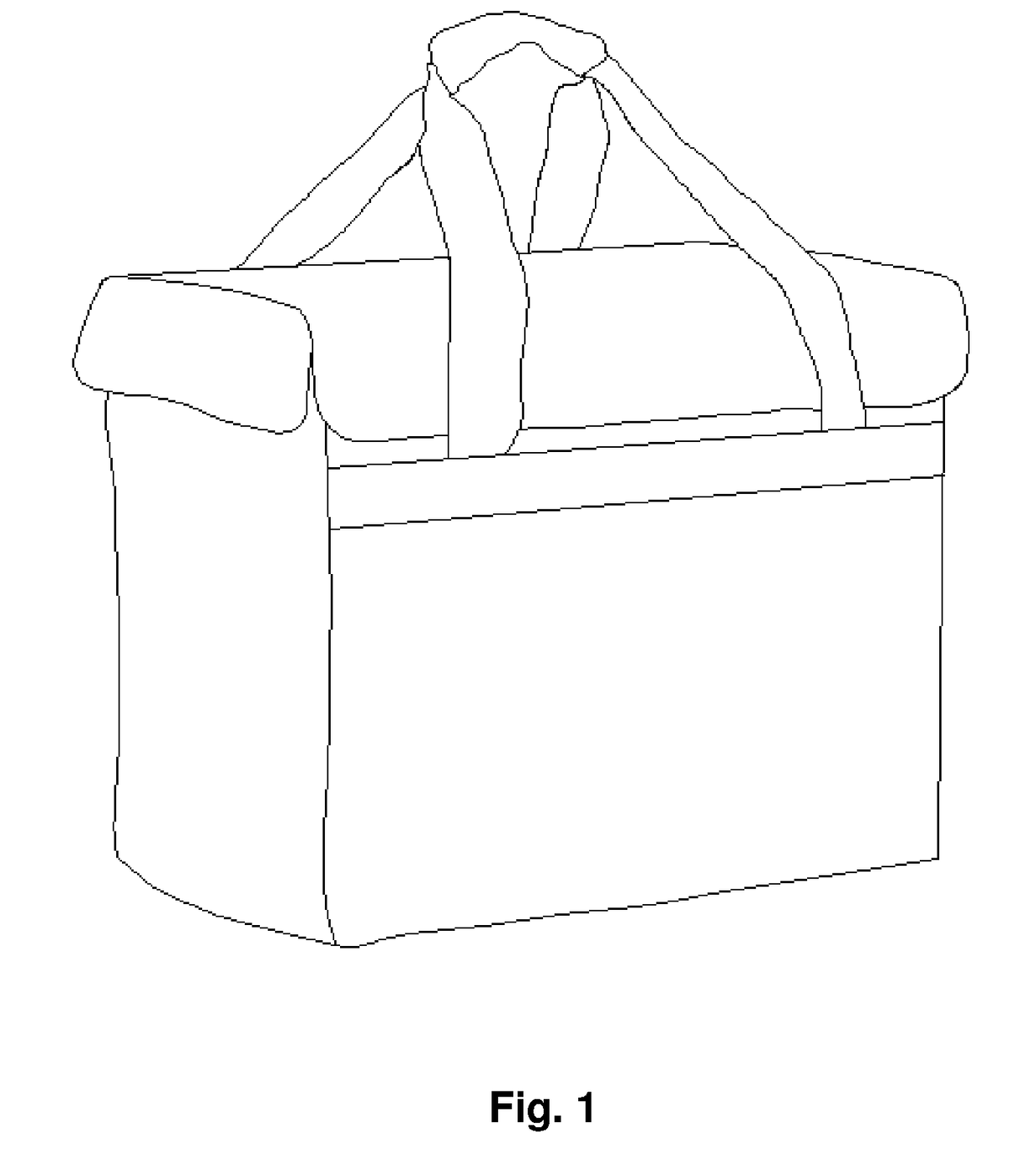
[0035]The embodiment discloses a foldable thermal insulation case, which specifically includes a case lid 1, a case body 2 and a liner 3.

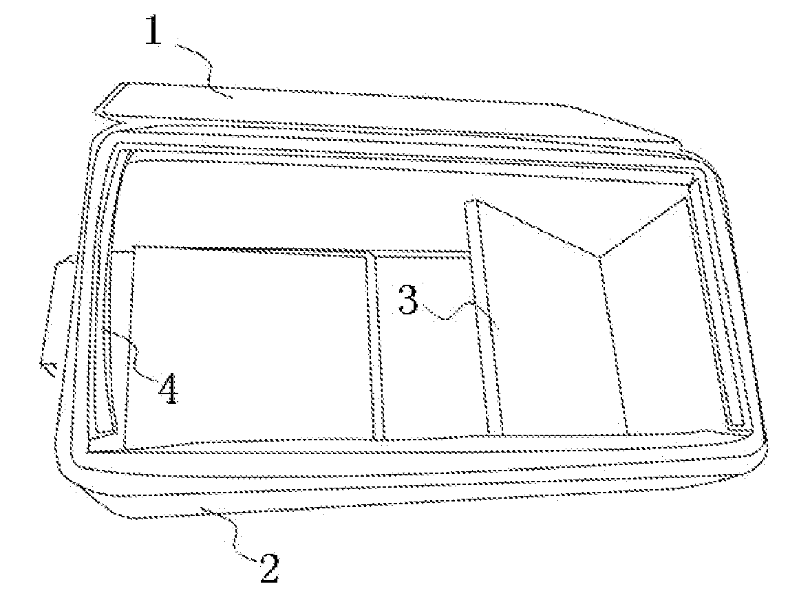
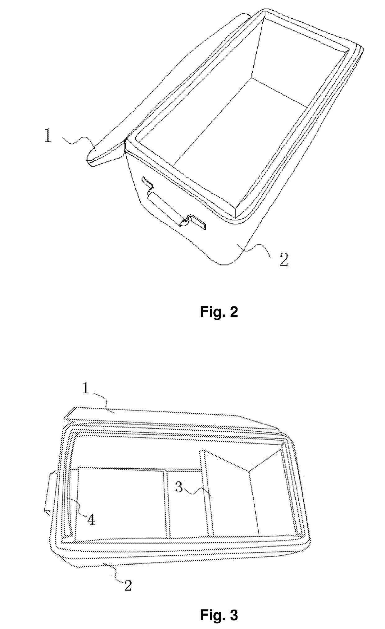
[0036]In an optional solution of the embodiment, the case lid 1 is covered on the case body 2, with a left side, a right side and a front side of the case lid 1 connected with the case body 2 by a connector, and a rear side of the case lid 1 connected integrally with the case body 2. More preferably, the connector is set as a zipper. Even more preferably, the connector is set as a waterproof zipper. Reference is made to both FIGS. 2 and 3.

[0037]To improve the thermal insulation performance of the case lid 1, i.e., to prevent energy from dissipating from the case lid 1, a cover plate is provided at a side of the case lid 1 near the case body 2, in which the cover plate is used to seal an upper opening of the liner 3 when the case body 2 is closed by the case lid 1. The cover plate may be connected with the case lid 1 by for example a Velcro, a zippe...

second embodiment

[0066]This embodiment is another preferred solution in parallel with the First Embodiment. The technical solutions disclosed in the First Embodiment, except for the following distinguishing technical feature, fall within the scope disclosed in this embodiment, and will not be repeated herein. This embodiment differs from the First Embodiment in that the liner 3 has a different structure, which is detailed as follows.

[0067]This embodiment provides a foldable thermal insulation case, which includes a case body 2, a case lid 1 and a liner 3. The liner 3 includes a bottom plate 31 and side plates 32. The bottom plate 31 and the side plates 32 provided around the bottom plate 31 define a cavity for accommodating an article. The side plates 32 may be bent downwards with respect to the bottom plate 31 and stacked on the bottom plate 31. There are a collapsed state and an unfolded state for the case body 2.

[0068]The bottom plate 31 is separable from each of the side plates 32, and each of t...


PUM


Abstract

The present invention relates to the field of thermal insulation devices, and particularly to a foldable thermal insulation case. It includes a case body, a case lid covered on the case body and a liner provided inside the case body. The liner includes a bottom plate corresponding to a bottom wall of the case body and side plates corresponding one to one to sidewalls of the case body. There are a collapsed state and an unfolded state for the liner. When the liner is in the unfolded state, each of the side plates stays upright around the bottom plate and is jointed with the bottom plate; in this way, the individual side plates and the bottom plate support the case body, and the case body is unfolded. When the liner is converted from the unfolded state into the collapsed state, that is, the side plates are bent downwards with respect to the bottom plate and stacked on the bottom plate, the case body may be folded downwards, and the size of the thermal insulation case is reduced after the case body is folded. Therefore, the invention enables the thermal insulation case to be folded, and the size of the thermal insulation case to be reduced effectively.

Description

TECHNICAL FIELD[0001]The present invention relates to the field of thermal insulation devices, and particularly to a foldable thermal insulation case.BACKGROUND ART[0002]In daily life, thermal insulation cases are needed to make foods, medicines and the like thermally insulated, transported or stored. Generally, the thermal insulation case includes a case body with an upper opening, and a case lid positioned on the top of the case body. A rear side of the case lid is fixedly connected with the case body, and a left side, a right side and a front side of the case lid are connected with the case body by a zipper. With such a structure design, the upper opening of the case body is closed. In general, the case body and the case lid each include an inner layer and an outer layer which are made of a waterproof material; alternatively, an intermediate layer made of a thermal insulation material is provided between the inner layer and the outer layer, to further improve the thermal insulati...

Claims


Application Information

Patent Timeline
IPC IPC(8): B65D81/38A45C13/10A45C11/20A61J1/16A45C7/00
CPCB65D81/3897A45C11/20A61J1/165A45C13/103A45C7/0077B65D7/24B65D25/02B65D81/3848
Inventor XIA, YONGHUIMA, ZHIJIANCAO, JINGLONG
Owner ZHEJIANG BIG NATURE OUTDOOR ARTICLE CO LTD
Learn More