Achromatic anastigmatic anamorphic objective

an anamorphic, objective technology, applied in the field of projection lenses, can solve the problems of reducing the number and range of wavelengths, affecting the focusing effect of wavelengths into the fluid stream, and requiring more complex and expensive objectives

Active Publication Date: 2018-01-18
COHERENT INC
View PDF1 Cites 14 Cited by
  • Summary
  • Abstract
  • Description
  • Claims
  • Application Information

AI Technical Summary

Problems solved by technology

An increasing number and range of wavelengths presents significant problems in the design and construction of an optical objective for focusing the combined laser-beam into the fluid-stream.
This could provide a problem in including UV wavelengths in a flow cytometer, as optical cements (adhesives) may be degraded by the UV radiation
Based on conventional optical design wisdom, it can be expec

Method used


Image

  • Achromatic anastigmatic anamorphic objective
  • Achromatic anastigmatic anamorphic objective
  • Achromatic anastigmatic anamorphic objective

Examples


Embodiment Construction

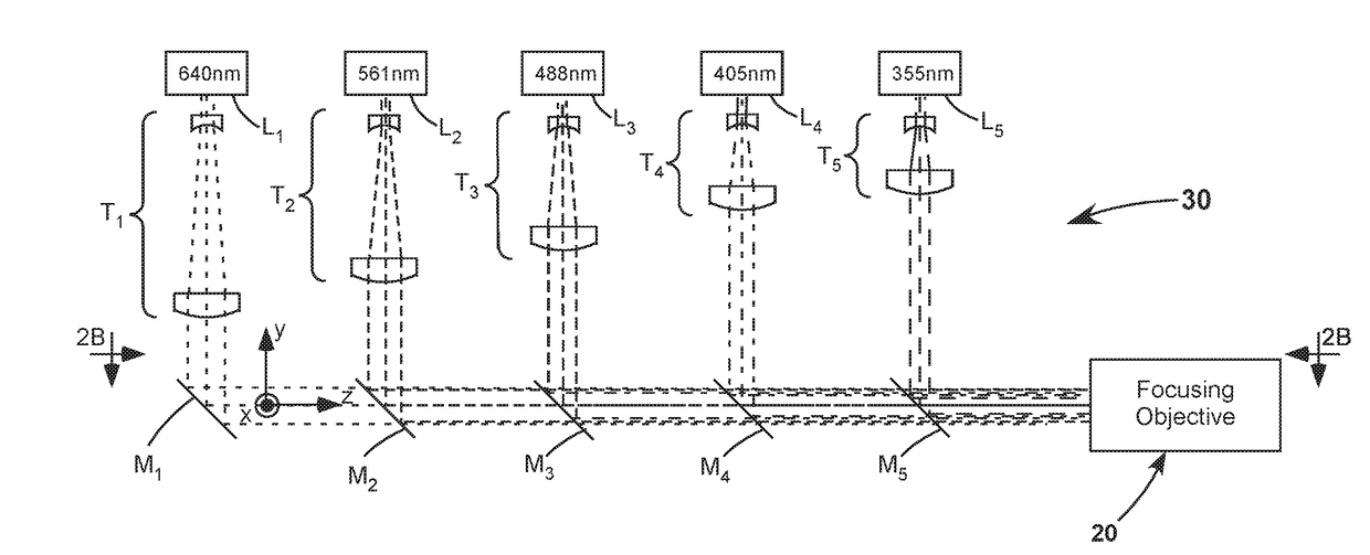
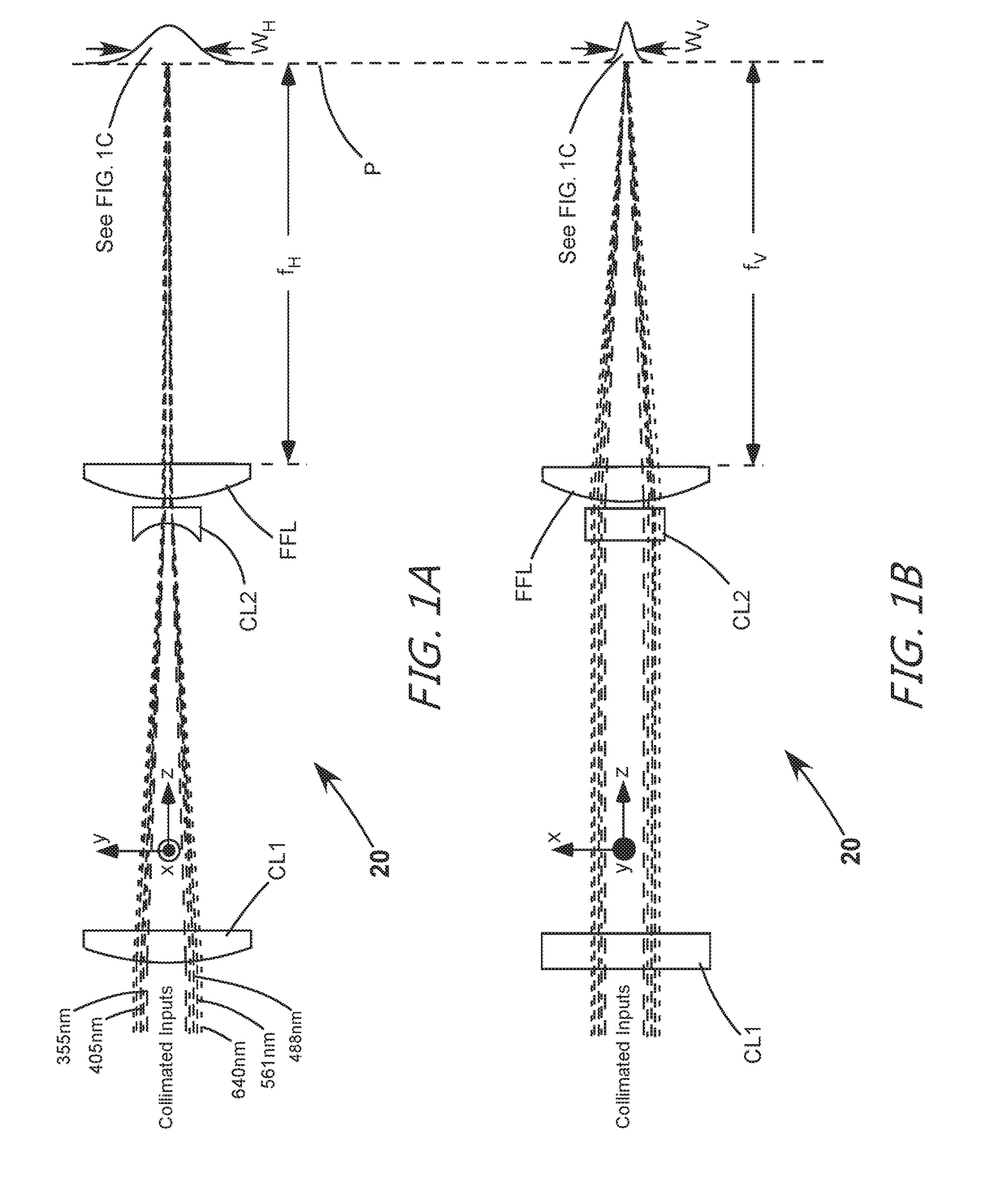
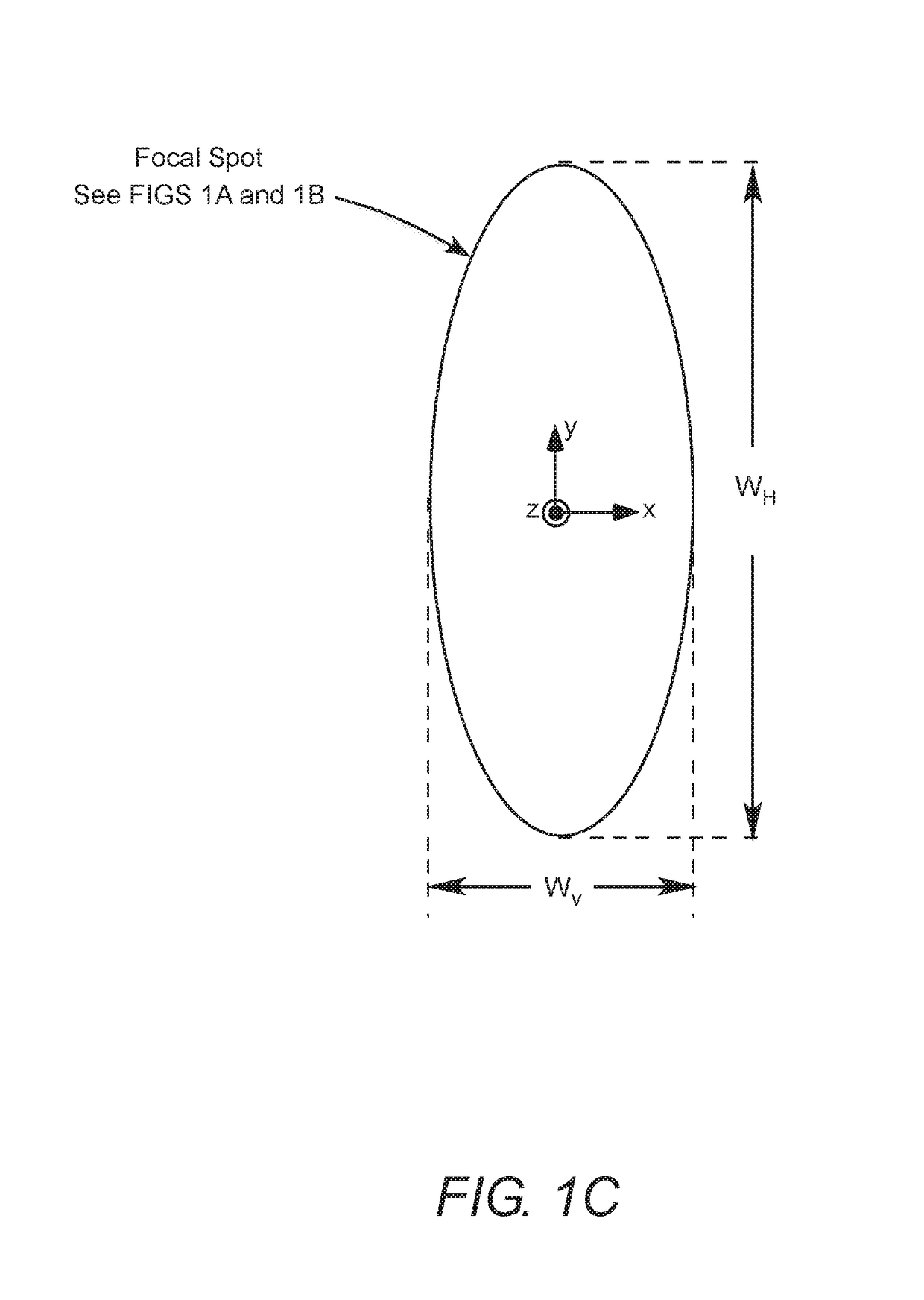
[0021]Turning now to the drawings, FIGS. 1A and 1B schematically illustrate a preferred embodiment 20 of an achromatic anastigmatic anamorphic focusing objective in accordance with the present invention. FIG. 1A is a view designated arbitrarily as a “horizontal” view. This is a view in a y-z plane defined by arbitrarily assigned Cartesian optical axes x, y, and z, where z is the propagation-axis (propagation direction) of light through the lens. FIG. 1B is a view designated arbitrarily as a vertical view, i.e., perpendicular to the view of FIG. 1A, i.e., a view in an x-z plane defined by the Cartesian optical axes.

[0022]Objective 20 includes cylindrical lens elements CL1 and CL2, having optical power in only the y-axis. Elements CL1 and CL2 are followed in the propagation-axis by final focusing element FFL. Element FFL has equal optical power in both the x-axis and the y-axis and be referred to generally as a rotationally symmetrical element. A spherical optical element is preferred...


PUM


Abstract

In a flow cytometer, an objective lens for focusing an input laser-radiation beam including at least four different laser-radiation wavelengths in a common plane includes only three singlet lens-elements. Two of the elements are cylindrical elements arranged as a cylindrical telescope for shaping and reducing the size of the input laser-beam. The third element is a spherical element arranged to focus the reduced size beam in the common plane. In one example, all three elements are made from the same optical material.

Description

PRIORITY[0001]This application claims priority to U.S. Provisional Application Ser. No. 62 / 363,532, filed Jul. 18, 2016, the disclosure of which is incorporated herein by reference in its entirety.TECHNICAL FIELD OF THE INVENTION[0002]The present invention relates in general to projection lenses. The invention relates in particular to anamorphic projection lenses for focusing two or more laser-beams having different wavelengths into a common elliptical focal-spot.DISCUSSION OF BACKGROUND ART[0003]A basic principle of flow cytometry is the passage of cells in a fluid-stream through a focused laser-beam so that the cells can be detected, identified, counted, and sorted. Cell components are fluorescently labelled and then excited by the laser-beam to emit light at varying wavelengths. The fluorescence can then be measured to determine the amount and type of cells present in a sample. Up to thousands of particles per second can be analyzed as they pass through the fluid-stream.[0004]Sev...

Claims


Application Information

Patent Timeline
IPC IPC(8): G02B13/08G02B9/16G02B27/09G01N15/14G02B27/14G02B27/10
CPCG02B13/08G02B27/145G02B27/1006G01N2015/1438G02B27/0905G02B27/0911G01N15/1434G02B9/16A61B5/0071G02B13/0035G02B27/0966G01N2015/1452
Inventor MENG, LEIWINZ, MICHELE WAYNE
Owner COHERENT INC
Why Eureka
Try Eureka