Optical coherence tomography for measurement on the retina

a coherence tomography and optical coherence technology, applied in the field of optical coherence tomography for examining samples, can solve the problems of inability to achieve diffraction-limited resolution, complicated alignment of devices, and increase in aberrations with numerical apertures, so as to achieve the effect of improving lateral resolution

Active Publication Date: 2018-01-25
CARL ZEISS MEDITEC AG
View PDF2 Cites 12 Cited by
  • Summary
  • Abstract
  • Description
  • Claims
  • Application Information

AI Technical Summary

Benefits of technology

[0010]The object of the invention is to specify an optical coherence tomograph for measurement on the retina of the human eye, in which the lateral resolution is improved without limiting the accessible depth area at the same time.
[0011]The invention combines several features in order to obtain, by application of optical coherence tomography, a three-dimensional image which has a particularly good resolution laterally, i.e. transverse to the optical axis, and at the same time can cover a very large depth area axially, i.e. along the optical axis, without the need to adjust focusing elements or lenses during the measurement process.

Problems solved by technology

This device is very complicated to align.
In addition, aberrations increase with the numerical aperture.
A diffraction-limited resolution can therefore not be achieved.

Method used


Image

  • Optical coherence tomography for measurement on the retina
  • Optical coherence tomography for measurement on the retina
  • Optical coherence tomography for measurement on the retina

Examples


Embodiment Construction

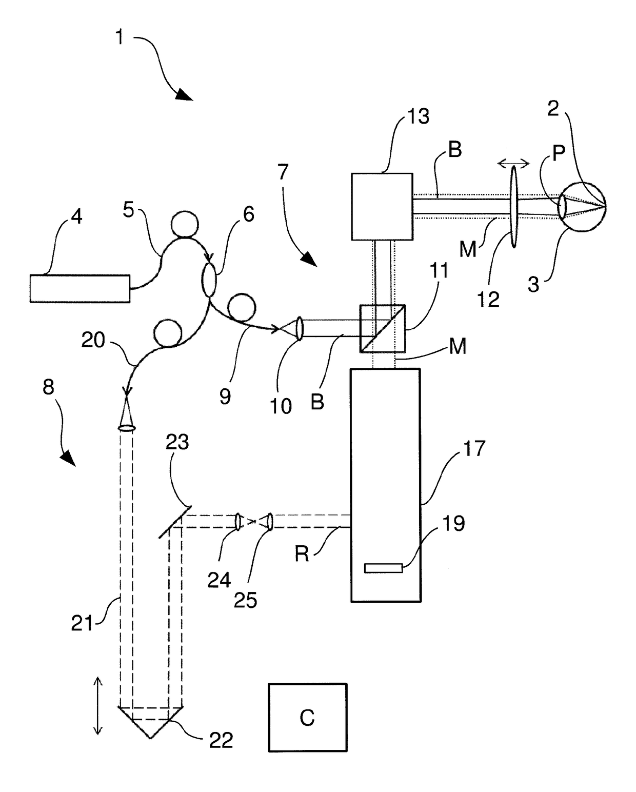
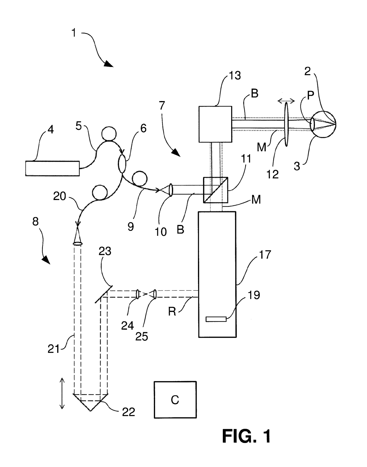
[0045]FIG. 1 shows an OCT 1 which captures three-dimensional images of a retina 2 of an eye 3. Source radiation of a radiation source 4 which is tunable with respect to its wavelength, for example of a corresponding laser, is coupled into a fiber 5. The source radiation is for example of infrared wavelength. In the following description this wavelength range is also called “light”. All radiation of the electromagnetic spectrum which satisfies the optical laws is to be subsumed under this term.

[0046]The fiber 5 feeds a splitter 6, which splits the source radiation into a measurement arm 7 and a reference arm 8. In the measurement arm 7 a fiber 9 follows the splitter 6, and the illumination radiation B emerging at the fiber end is guided to a beam splitter 11 by means way of an illumination optical system 10. From there it reaches a front optics 12, which bundles the illumination radiation B into a focus which lies on the retina 2 of the eye 3. The illumination optical system 10 and t...


PUM


Abstract

An optical coherence tomograph that provides wavelength tunable source radiation and an illumination and measurement beam path, a dividing element that divides source radiation into illumination radiation and reference radiation, and collects measurement radiation. The illumination and measurement beam path has scanner. A detection beam path receives measurement radiation and reference radiation and conducts them onto at least one flat panel detector in a superposed manner. A beam splitter separates the measurement radiation from the illumination radiation. The beam splitter conducts the separated measurement radiation to the detection beam path and sets the numerical aperture of the illumination of the illumination field in the eye. An optical element sets the numerical aperture with which the measurement radiation is collected in the eye and a multi-perforated aperture defines the size of an object field and a number of object spots, from which the measurement radiation reaches the flat panel detector.

Description

RELATED APPLICATIONS[0001]The present application is a National Phase entry of PCT Application No. PCT / EP2015 / 051834, filed Jan. 28, 2016, which claims priority from DE Patent Application No. 10 2015 101 251.0, filed Jan. 28, 2015, both of said applications being hereby incorporated by reference herein in their entirety.FIELD OF INVENTION[0002]The invention relates to an optical coherence tomograph for examining a sample, in particular an eye.[0003]Further, the invention relates to a method for optical coherence tomography for examining a sample, in particular an eye.BACKGROUND[0004]In optical coherence tomography OCT systems the lateral resolution (x and y) is defined by the numeral aperture (NA) of the optical system used. The axial resolution (z), however, is calculated from an interference pattern and as a rule is much greater than the depth of field of the imaging, which in turn depends on the numerical aperture, more precisely is proportional to 1 / NA2. In the usually used Four...

Claims


Application Information

Patent Timeline
Patent Type & Authority Applications(United States)
IPC IPC(8): A61B3/10G01B9/02
CPCA61B3/102G01B9/02004G01B9/02091G01B9/02041G01B9/0205G01B9/02034G01B2290/45
Inventor BUBLITZ, DANIELNIETEN, CHRISTOPH
Owner CARL ZEISS MEDITEC AG
Why Eureka
Try Eureka