Radiator System

a radiator and radiator technology, applied in the direction of machines/engines, liquid fuel engines, transportation and packaging, etc., can solve the problems of radiator failure, radiator failure, radiator failure, etc., to improve structural integrity, reduce the likelihood of failure, the effect of reducing the likelihood of failur

Active Publication Date: 2018-01-25
SHIHEIBER NIMER IBRAHIM
View PDF23 Cites 15 Cited by
  • Summary
  • Abstract
  • Description
  • Claims
  • Application Information

AI Technical Summary

Benefits of technology

[0014]Improved radiator systems according to preferred embodiments of the invention provide improved structural integrity and reduce the likelihood of failure compared to prior art radiators. They also reduce or eliminate the need to install accessories to the inner fender or firewall and provide greater flexibility in installing the radiator system in the engine compartment. Cooling efficiency is greatly increased by increased air flow through the core cavity, by creating a circulating vortex pattern for the air, and by directing air through the core cavity without pull-back. Cooling efficiency is also increased by incorporating multiple heat exchange elements into the system, in addition to the heat exchange through the radiator core. For example, vortex tubes through the heat exchange core tanks, the self-circulating cooling system, and the front grill all act to exchange heat between the coolant and air or to dissipate heat away from the radiator system.

Problems solved by technology

This results in stress and fatigue to the core seams, particularly with flexing, rattling and shaking during use of the automobile, which leads to radiator failure.
Generally, the radiator is not a perfect fit and must be forced into position to align with the brackets and dimples, which puts stress on the radiator.
In time, with grease, solvent, coolant and natural extremities, these non-vulcanized, rubber saddles will swell-up and pop out of place, causing radiator failure.
It is not desirable to put holes for mounting accessories in the inner fender or firewall, particularly in classic vehicles.
Additionally, the shroud on prior art radiators does not create a sealed air cavity.
This allows air to enter the core from the wrong direction, decreasing cooling efficiency and making the fan system work harder.
Prior art radiators are typically made from aluminum parts, which are subject to deterioration from electrolysis.
Sometimes the radiator cap will include a chain with zinc on in that can be useful in reducing damage from electrolysis, but it is usually insufficient.

Method used


Image

  • Radiator System
  • Radiator System
  • Radiator System

Examples


Embodiment Construction

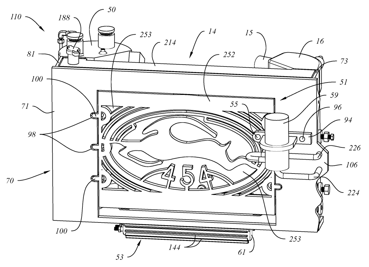
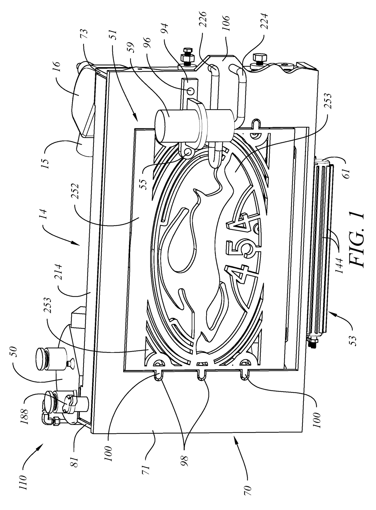
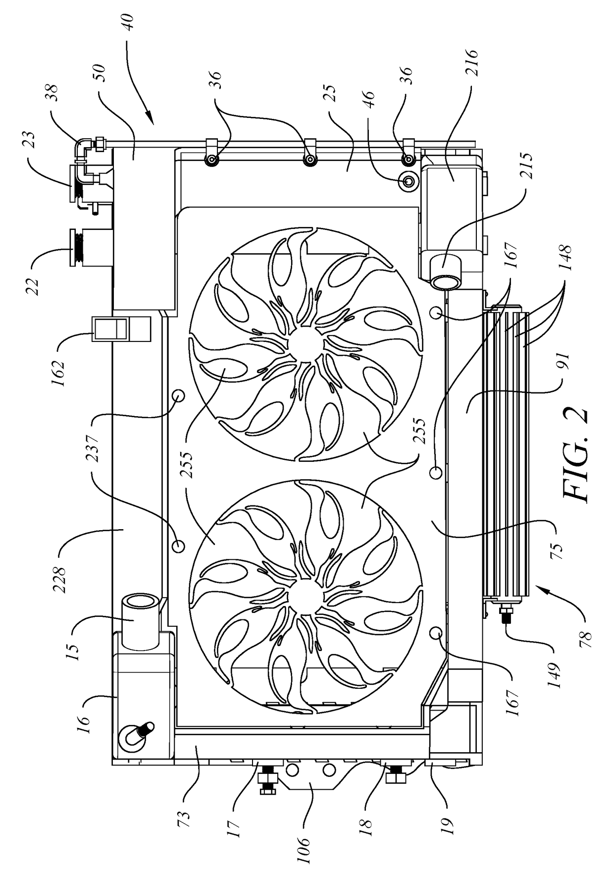
[0034]Referring to FIGS. 1-11, a preferred embodiment for radiator system 110 is shown. Radiator system 110 preferably comprises a mounting frame 70, decorative front grill 51, external transmission cooler 53, internal transmission cooling tube 34, external power steering / hydro brake cooling system 78, power steering / hydro-boost brake system reservoir 59, rear grill 75, self-circulating cooling system 20, a windshield wiper reservoir system 41, an internal fan system, a right heat exchange core tank 80, a left heat exchange core tank 82, upper shroud 14, a frame mounting system, and an optional secondary coolant pump system 151 (shown in FIGS. 12-14). Radiator system 110 also preferably comprises a control system to activate fans and optional coolant pumps, open and close valves, and send and receive signals and data based on sensor measurements, such as coolant temperature.

[0035]Referring to FIGS. 1-3, mounting frame 70 comprises a substantially rectangular front body 71 with a cen...


PUM


Abstract

An improved radiator mounting and cooling system for use in automobiles allows multiple components to be incorporated into the same unit, limiting the need for accessories to be mounted to inner fenders or firewall. A circulating vortex of air is pulled through a front grill and vortex tubes disposed through sides of the radiator system to improve cooling efficiency. An outer shroud protects interior components and creates a sealed core cavity allowing air to only enter through vortex tubes and front grill and exit through a rear grill. A self-circulating cooling system provides additional cooling of coolant. A fan system pulls around 5000 CFM of air through the core cavity. An optional secondary coolant pumping system allows coolant to be pumped when needed. A control system controls activation of the fan system and secondary coolant pumping system based on signals from sensors.

Description

CROSS REFERENCE TO RELATED APPLICATIONS[0001]This application claims the benefit of U.S. Provisional Application Ser. Nos. 62 / 365,683 and 62 / 365,771 both filed on Jul. 22, 2016.BACKGROUND OF THE INVENTION1. Field of the Invention[0002]This invention relates to an improved radiator system for use in automobiles. Multiple components are incorporated into a single system and mounting frame, limiting the need for accessories to be mounted to inner fenders or firewall. Air is directed through a core cavity in a circulating vortex pattern.2. Description of Related Art[0003]Prior art automobile radiators comprise two heat exchange core tanks and a core made of a tubes through which hot coolant flows from one heat exchange core tank to the other. Air passes over the core tubes to cool the coolant inside the tubes. The cooled coolant is transferred from the cool heat exchange core tank to the engine to cool the engine and is then returned to the hot heat exchange core tank to be cooled in th...

Claims


Application Information

Patent Timeline
Patent Type & Authority Applications(United States)
IPC IPC(8): B60K11/04F01P3/12
CPCB60K11/04F04D25/066F04D25/082F01P3/12F04D19/002F04D29/601B60K11/06F01P3/18
Inventor SHIHEIBER, NIMER IBRAHIM
Owner SHIHEIBER NIMER IBRAHIM
Why Eureka
Try Eureka