Image-sensor structures

Inactive Publication Date: 2018-01-25
VISERA TECH CO LTD
View PDF4 Cites 10 Cited by
  • Summary
  • Abstract
  • Description
  • Claims
  • Application Information

AI Technical Summary

Problems solved by technology

However, these two pixels lose half of the incoming light, les

Method used


Image

  • Image-sensor structures
  • Image-sensor structures
  • Image-sensor structures

Examples


Embodiment Construction

[0023]The following description is of the best-contemplated mode of carrying out the invention. This description is made for the purpose of illustrating the general principles of the invention and should not be taken in a limiting sense. The scope of the invention is best determined by reference to the appended claims.

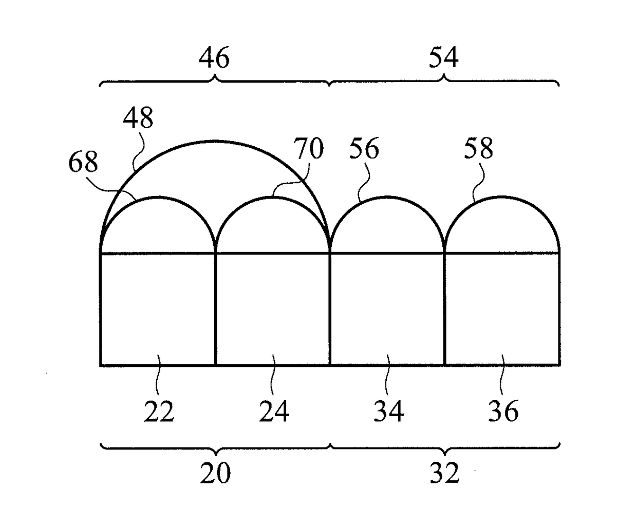
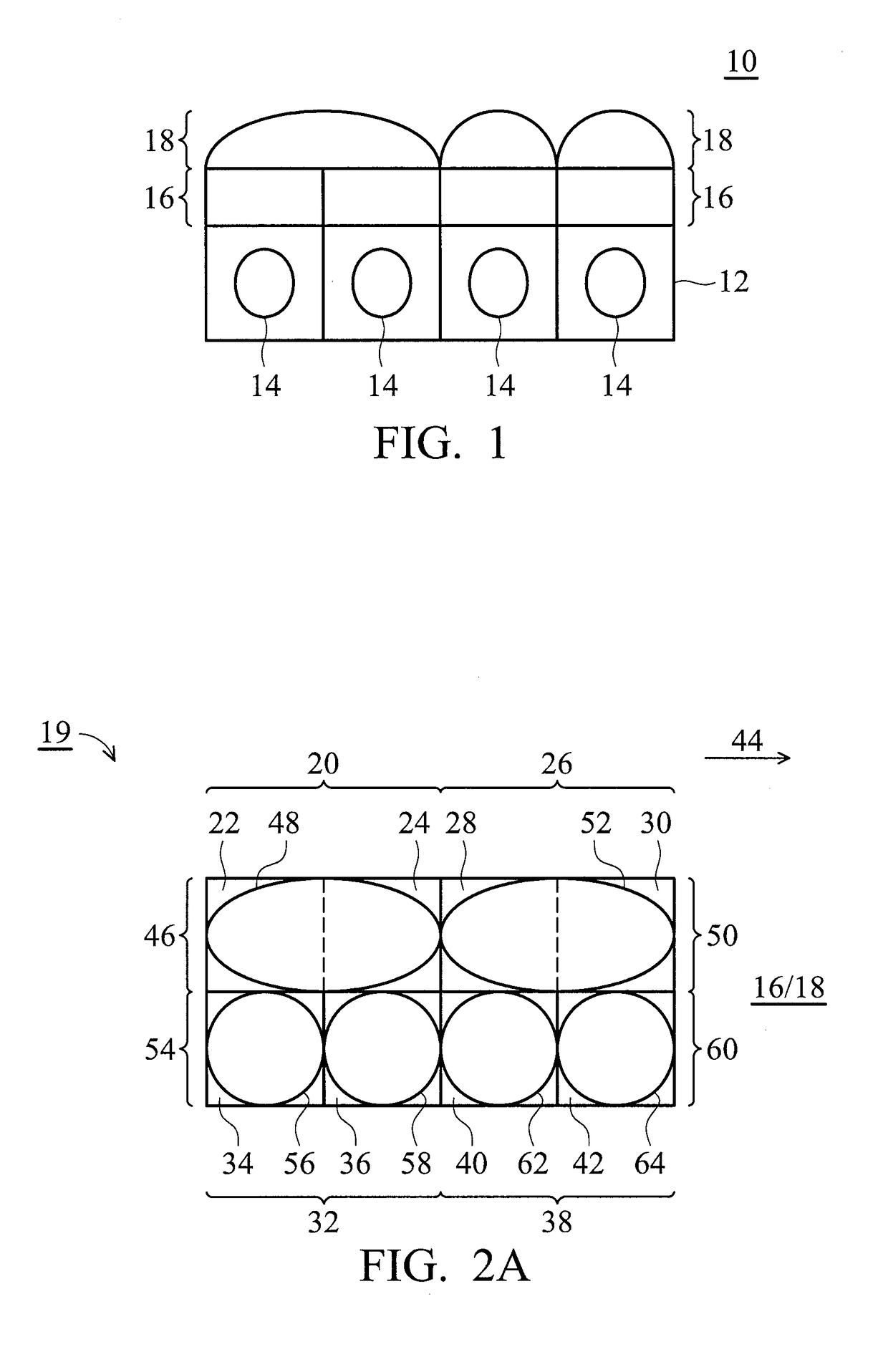
[0024]Referring to FIG. 1, in accordance with one embodiment of the invention, an image-sensor structure 10 is provided. FIG. 1 is a cross-sectional view of the image-sensor structure 10.

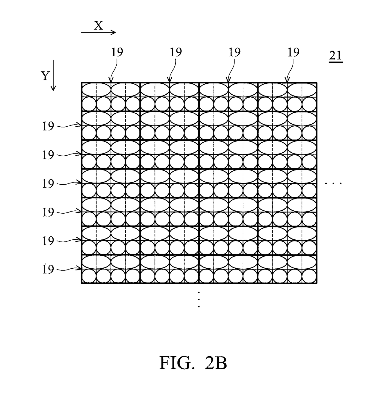
[0025]The image-sensor structure 10 comprises a substrate 12, a plurality of photoelectric conversion units 14 formed in the substrate 12, a plurality of color filter patterns 16 formed above the substrate 12 and the photoelectric conversion units 14, and a plurality of microlenses 18 formed above the color filter patterns 16. In some embodiments, top views of various arrangements of the color filter patterns 16 and profiles of the microlenses 18 of various pixel units 19 and 19′ of th...


PUM


Abstract

An image-sensor structure is provided. The image-sensor structure includes a plurality of color filter patterns divided into a first unit including one green filter, a second unit including one green filter, a third unit including one blue filter, and a fourth unit including one red filter, wherein the first unit is adjacent to the second unit; and a plurality of microlenses formed above the color filter patterns, wherein the microlenses are divided into a first microlens unit having one microlens above the one green filter of the first unit and the one green filter of the second unit, a second microlens unit above the one blue filter of the third unit, and a third microlens unit above the one red filter of the fourth unit.

Description

BACKGROUND OF THE INVENTIONField of the Invention[0001]The invention relates to an image-sensor structure, and more particularly to an image-sensor structure with shared microlenses.Description of the Related Art[0002]An image sensor is a kind of semiconductor device that transforms photons into electrical signals. Image sensors can be generally classified into charge coupled devices (CCDs) and complementary metal oxide semiconductor (CMOS) image sensors. Among these image sensors, a CMOS image sensor comprises a photodiode for detecting incident light and transforming it into electrical signals, and logic circuits for transmitting and processing the electrical signals.[0003]Recently, phase detection autofocus (PDAF) technology has been introduced into DSLR, DSC and Smart Phone Cameras. The principle is to have a pair of half opaque green pixels with a whole microlens thereabove. The differential signals of both green pixels create the phase detection autofocus function. However, th...

Claims


Application Information

Patent Timeline
IPC IPC(8): H01L27/146
CPCH01L27/14627H01L27/14621H01L27/14643H01L27/14605
Inventor HSIEH, CHIN-CHUANWANG, WEI-KO
Owner VISERA TECH CO LTD
Why Eureka
Try Eureka