Systems and methods for delivering an intravascular device to the mitral annulus

a technology of mitral annulus and system, applied in the field of implantable cardiac devices, to achieve the effect of increasing the flexibility of the hypotub

Active Publication Date: 2018-02-01
CEPHEA VALVE TECH
View PDF9 Cites 39 Cited by
  • Summary
  • Abstract
  • Description
  • Claims
  • Application Information

AI Technical Summary

Benefits of technology

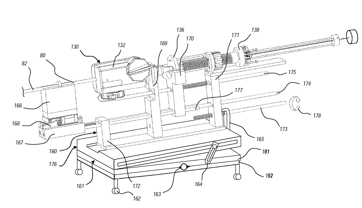
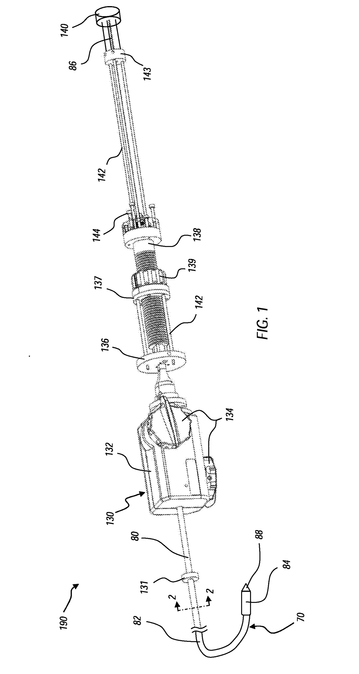
[0007]In some embodiments, the steering component is a steering catheter nested within the outer sheath. The steering catheter may include a plurality of tension cables and corresponding tension cable lumen, the tension cables providing for steering of the steering catheter by adjusting tension in the tension cables. The steering catheter may be formed as a hypotube, the hypotube having a cut pattern that increases the flexibility of the hypotube relative to an uncut section of hypotube. The steering catheter may include a plurality of microfabricated cuts along at least a proximal section of the distal piece, the microfabricated cuts being configured to provide bending in a single plane.

Problems solved by technology

An intravascularly delivered device needs to be placed precisely to ensure a correct positioning of the medical device, which is essential for its functionality, as the device may be difficult to reposition after the device is fully deployed from the delivery system.

Method used


Image

  • Systems and methods for delivering an intravascular device to the mitral annulus
  • Systems and methods for delivering an intravascular device to the mitral annulus
  • Systems and methods for delivering an intravascular device to the mitral annulus

Examples


second embodiment

[0083]While the illustrated embodiment uses cooperating flanges, rings and / or ridges, other suitable elements can also be used to accomplish the same functions, including, but not limited to rings, welds, detents, or other suitable structures. The first swivel connection 450 can also include one or more o-rings or other sealing components (not shown) positioned between the cooperating elements of the swivel to provide a fluid-tight swivel connection. first swivel connection 450 is illustrated in FIG. 12.

[0084]Similarly, as further illustrated in FIG. 12, a second swivel connection 452 can also be formed at the proximal end of the sheath to rotationally decouple the delivery sheath 82 from the control fixture 454 (shown schematically only). Second swivel connection 452 can include a pair of spaced-apart, annular ridges 456a and 456b formed on the exterior surface and adjacent to the proximal end of hypotube 442. Annular ridges 456a and 456b form an annular recess 458 between which a ...


PUM

PropertyMeasurementUnit
bend radiusaaaaaaaaaa
bending radiusaaaaaaaaaa

Abstract

The present disclosure describes devices, systems, and methods for intravascularly delivering an implantable device at the mitral annulus. A delivery system includes a delivery member coupled to a handle assembly and extending distally from the handle assembly. The intravascular device is attached at the distal end of the delivery member, and is housed within a distal piece of an outer sheath. A steering catheter is nested within the outer sheath to bend the delivery member into position. A delivery catheter is configured to advance the intravascular device relative to the outer sheath, and a suture catheter includes sutures/tethers which may be coupled to the intravascular device prior to deployment.

Description

CROSS-REFERENCE TO RELATED APPLICATIONS[0001]This application claims the benefit of and priority to: U.S. Provisional Patent Application Ser. No. 62 / 368,683, filed on Jul. 29, 2016 and titled “Intravascular Device Delivery Sheath”; U.S. Provisional Patent Application Ser. No. 62 / 368,695, filed on Jul. 29, 2016 and titled “Threaded Coil”; U.S. Provisional Patent Application Ser. No. 62 / 368,702, filed on Jul. 29, 2016 and titled “Combination Steerable Catheter and Systems”; U.S. Provisional Patent Application Ser. No. 62 / 368,711, filed on Jul. 29, 2016, and titled “Hypotube Reinforced Intravascular Device Delivery Systems and Methods”; U.S. Provisional Patent Application Ser. No. 62 / 380,246, filed on Aug. 26, 2016 and titled “Rotational Fixation of Catheters”; U.S. Provisional Patent Application Ser. No. 62 / 380,795, filed Aug. 29, 2016 and titled “Systems and Methods for Loading and Deploying an Intravascular Device”; U.S. Provisional Patent Application Ser. No. 62 / 380,799, filed Aug....

Claims


Application Information

Patent Timeline
Patent Type & Authority Applications(United States)
IPC IPC(8): A61B17/04A61F2/24A61M25/00A61M25/09A61M25/01A61M25/06
CPCA61B17/0469A61M25/0136A61M25/0662A61M25/0054A61F2/2436A61M25/0045A61M25/09A61M25/0147A61M25/005A61F2/2439A61M25/0138A61M2025/0175A61M25/0097A61M2025/0004A61F2/9517
Inventor VAN OEPEN, RANDOLFMCNIVEN, SEAN A.VALENCIA, FRANCISCO
Owner CEPHEA VALVE TECH
Why Eureka
Try Eureka