Method of construction, assembly, and launch of a floating wind turbine platform

a technology of wind turbines and platforms, which is applied in the field of wind turbine platforms, can solve the problems of unsatisfactory aesthetics, unsatisfactory wind turbines, and inability to achieve the optimal flow of air on land

Active Publication Date: 2018-02-01
UNIVERSITY OF MAINE
View PDF7 Cites 19 Cited by
  • Summary
  • Abstract
  • Description
  • Claims
  • Application Information

AI Technical Summary

Benefits of technology

[0006]This invention relates in general to methods of constructing, assembling, and launching floating wind turbine platforms and the wind turbines mounted thereon. In particular, this invention relates to an improved method of constructing, assembling, and launching a floating wind turbine platform wherein at least a portion of the wind turbine platform; e.g., the base, the hull without top beams, the hull with top beams, or the entire floating wind turbine platform wit

Problems solved by technology

These large groups of wind turbines can generate undesirably high levels of noise and may be viewed as aesthetically unpleasing.
An optimum flow of air may not be available to these land-base wind turbines due to obstacles such as hills, woods, and buildings.
The foundations required to attach wind turbines to the seabed at th

Method used


Image

  • Method of construction, assembly, and launch of a floating wind turbine platform
  • Method of construction, assembly, and launch of a floating wind turbine platform
  • Method of construction, assembly, and launch of a floating wind turbine platform

Examples


first embodiment

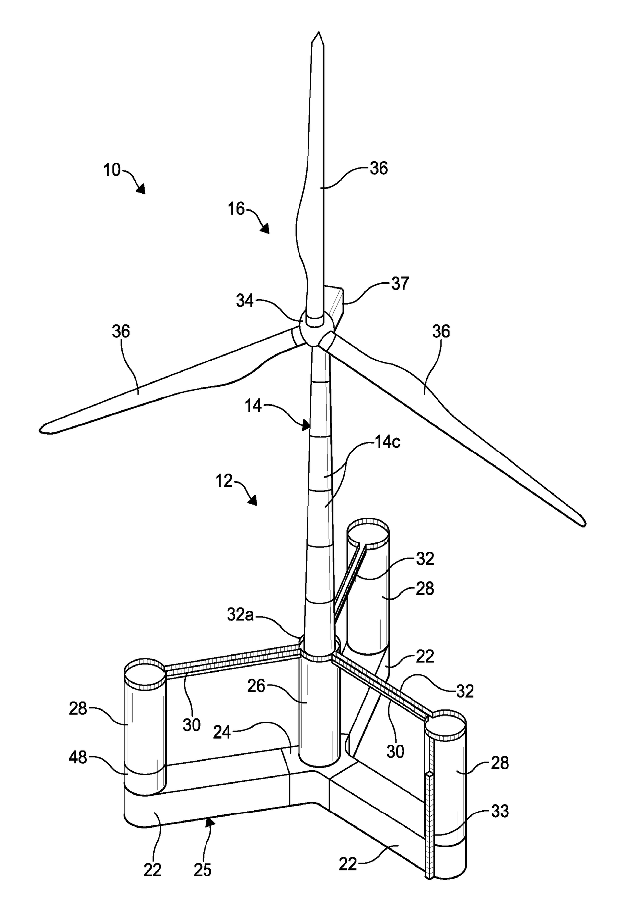
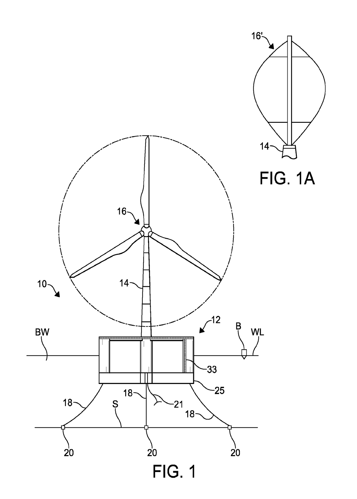
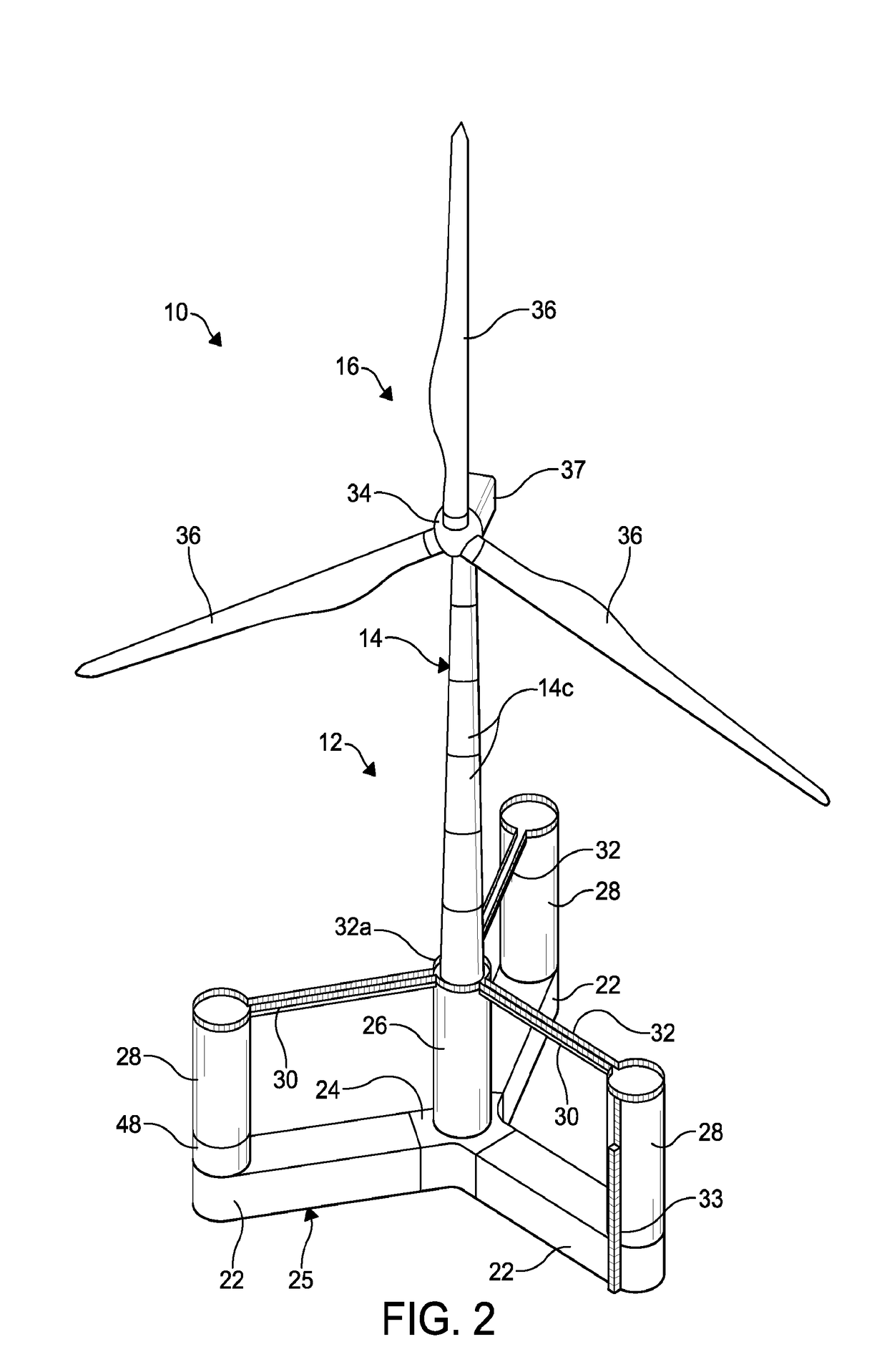
[0032]Referring to the drawings, particularly to FIG. 1, a floating wind turbine system or platform 10 is shown anchored to a bed of a body of water BW. The floating wind turbine platform is representative of a wind turbine platform that has been constructed and assembled in accordance with the improved method of this invention. In the illustrated embodiment, the floating wind turbine platform 10 is shown anchored to the seabed S. It will be understood that the seabed may be the bed of any body of water in which the floating wind turbine platform 10 will be placed into operation.

[0033]The illustrated floating wind turbine platform 10 includes a foundation or hull 12 that supports a tower 14, described below in detail. The tower 14 supports a wind turbine 16. The foundation is semi-submersible, and is structured and configured to float, semi-submerged, in a body of water. Accordingly, a portion of the hull 12 will be above water when the hull 12 is floating in the water. As shown, a ...

second embodiment

[0050]the hull is shown at 70 in FIG. 4. As shown in FIG. 4, the hull 70 includes a base 72, also shown in FIG. 5, comprising three buoyant bottom beams 74 that extend radially outwardly from a keystone 76. A center column 78 is mounted to the keystone 76, and three outer columns 80 are mounted at or near the distal ends of the bottom beams 74. Although three buoyant bottom beams 74 are shown in FIG. 4, it will be understood that the hull 70 may include more than three buoyant bottom beams 74.

[0051]As described in detail below, the bottom beams 74 may be formed from a plurality of beam sections 82 and a column base section 84, upon which the outer columns 80 are mounted. The bottom beams 74 may be formed from any desired number of beam sections 82, such as the six beam sections 82 illustrated in FIG. 4, less than six beam sections 82, or more than six beam sections 82. If desired, the keystone 76 may also be formed in any desired number of sections (not shown).

[0052]As also describe...

third embodiment

[0088]Referring now to FIG. 15, a method of constructing, assembling, and launching the floating wind turbine platform 10, or a portion thereof, is shown at M3.

[0089]As shown in FIG. 15, the construction and assembly of bottom beams 74 and wings 75 in one or more construction and assembly areas A3 on shore near a body of water BW having a shoreline SL. As used herein, a wing 75 is defined as a bottom beam 74 with the keystone 76 attached thereto.

[0090]The construction and assembly areas A3 may be located at any desired location and is connected to a method of moving the bottom beams 74 and wings 75 from and through the construction and assembly areas A3 and to the shoreline SL. As shown in FIG. 15, the shoreline SL may be defined by the dock D. The bottom beams 74 and wings 75 may be assembled on a platform (not shown) configured to move on a system of longitudinally extending rails, schematically illustrated at 142. The rails 142 extend substantially parallel with the shoreline SL ...


PUM


Abstract

A method of constructing and assembling a floating wind turbine platform includes constructing pre-stressed concrete sections of a floating wind turbine platform base, assembling the floating wind turbine platform base sections to form the base at a first location in a floating wind turbine platform assembly area, and moving the base to a second location in the floating wind turbine platform assembly area. Pre-stressed concrete sections of floating wind turbine platform columns are constructed, and the column sections are assembled to form a center column and a plurality of outer columns on the base to define a hull at the second location in the floating wind turbine platform assembly area. The hull is then moved to a third location in the floating wind turbine platform assembly area. Secondary structures are mounted on and within the hull, and the hull is moved to a fourth location in the floating wind turbine platform assembly area. A wind turbine tower is constructed on the center column, and a wind turbine is mounted on the wind turbine tower, thus defining the floating wind turbine platform. The floating wind turbine platform is then moved to a launch platform in a fifth location and launched into a body of water.

Description

CROSS-REFERENCE TO RELATED APPLICATIONS[0001]This application claims the benefit of U.S. Provisional Application Nos. 62 / 120,081, filed Feb. 24, 2015, and 62 / 149,947, filed Apr. 14, 2015 the disclosures of which are incorporated herein by reference.BACKGROUND OF THE INVENTION[0002]This invention relates in general to wind turbine platforms. In particular, this invention relates to an improved method of constructing, assembling, and launching a floating wind turbine platform into a body of water.[0003]Wind turbines for converting wind energy to electrical power are known and provide an alternative energy source for power companies. On land, large groups of wind turbines, often numbering in the hundreds of wind turbines, may be placed together in one geographic area. These large groups of wind turbines can generate undesirably high levels of noise and may be viewed as aesthetically unpleasing. An optimum flow of air may not be available to these land-base wind turbines due to obstacle...

Claims


Application Information

Patent Timeline
IPC IPC(8): F03D13/25
CPCF03D13/25B63B1/107B63B21/50B63B5/20B63B2021/505B63B2035/446B63B35/44B63B35/003F03D13/40F05B2240/93F05B2240/95F03D13/10B63B2001/128B63B39/03Y02E10/727Y02E10/72
Inventor VISELLI, ANTHONY M.DAGHER, HABIB J.
Owner UNIVERSITY OF MAINE
Why Eureka
Try Eureka