
Method and apparatus for simulating the generated charge profile of piezoelectric elements due to arbitrary shock loading

a piezoelectric element and generated charge technology, applied in the direction of piezoelectric/electrostrictive device details, instruments, device details, etc., can solve the problems of high cost and time consumption, particularly in the simulation of computer models, and the short-lived charge generated by piezoelectric transducers

Active Publication Date: 2018-02-01
OMNITEK PARTNERS LLC
View PDF3 Cites 0 Cited by
  • Summary
  • Abstract
  • Description
  • Claims
  • Application Information

AI Technical Summary

Benefits of technology

The patent text describes a need for electronic devices that can simulate the energy generated by piezoelectric devices used for energy harvesting or detecting events like shock loading. This is important because it allows developers to test their devices without having to integrate them into a larger system, which can be time-consuming and costly. The simulator should be programmable to produce realistic output and should be able to mimic the energy profile of piezoelectric devices under various input loading. This would provide a more efficient and reliable way to develop and test these devices.

Problems solved by technology

In such cases, the charges generated by the piezoelectric transducer are typically short lived and proper electronic circuitry has to be developed that could collect the generated charges and condition it for use by the system or device to be powered and / or for storage in an appropriate electrical energy storage device such as a rechargeable battery or a capacitor or the like.
Design of aforementioned efficient charge collection and conditioning circuits is particularly challenging in applications such as gun-fired munitions which require additional safety features to prevent accidental powering of the devices being powered, such as their initiation devices.
Thus, computer modeling and simulation process is very helpful to the circuit designer at the early stages of the circuit development efforts but due to unavoidable effects of approximations and idealizations of the component used in the circuits and the neglected effects of nonlinearities, cross-sensitivities, connecting wires and connectors, and many other factors that are either idealized or approximated or totally ignored while modeling a complex system, the results of simulation of computer models is generally good only up to certain limits.

Method used


Image

  • Method and apparatus for simulating the generated charge profile of piezoelectric elements due to arbitrary shock loading
  • Method and apparatus for simulating the generated charge profile of piezoelectric elements due to arbitrary shock loading
  • Method and apparatus for simulating the generated charge profile of piezoelectric elements due to arbitrary shock loading

Examples


Embodiment Construction

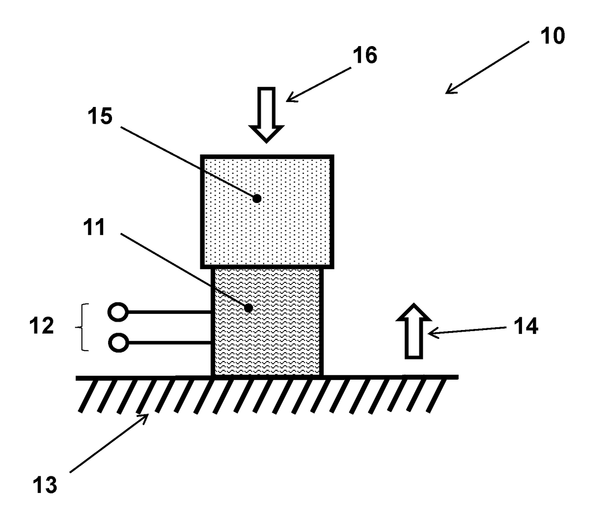
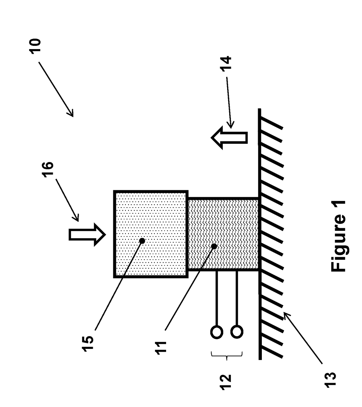
[0025]A typical piezoelectric electrical energy generator 10, usually with a stack type piezoelectric element 11, that is used in self-powered devices to generate electrical energy when the device is subjected to shock loading, for example due to an acceleration pulse, is shown in the schematic of FIG. 1. In the configuration shown in FIG. 1, the piezoelectric electrical energy (charge) generator 10 is shown as rigidly attached to a base structure 13, which is considered to be subjected at certain point in time to an acceleration pulse in the direction of the arrow 14. A relatively rigid mass 15 may also be required to react to the acceleration 14 and apply a resulting compressive force to the piezoelectric element 11. Then because of the compressive force and the internal normal compressive pressure generated in the piezoelectric element 11 due to its own mass because of the acceleration, the piezoelectric element 11 is strained axially, and thereby generates electrical charges at ...


PUM


Abstract

A piezoelectric open-circuit output voltage profile simulator including a capacitor; at least first, second and third switches; and a controller for controlling the first, second and third switches.

Description

CROSS-REFERENCE TO RELATED APPLICATION[0001]This application claims the benefit of U.S. Provisional Application No. 62 / 367,074 filed on Jul. 26, 2016, the entire contents of which is incorporated herein by reference.BACKGROUND1. Field[0002]The present disclosure relates generally to methods for the design of electronic simulators that can simulate the profile of the level of charges generated when a piezoelectric element is subject to shock loading and to a related apparatus. The present disclosure is more particularly related to simulators that can simulate the profile of the level of charges generated by piezoelectric elements used in munition during firing or target impact.2. Prior Art[0003]Pulsed loading of piezoelectric transducers occurs in many applications such as those in munitions firing or when a mechanical system is subjected to impact type loading and is used to generate electrical energy. In such cases, the charges generated by the piezoelectric transducer are typicall...

Claims


Application Information

Patent Timeline
Patent Type & Authority Applications(United States)
IPC IPC(8): G06F17/50H01L41/113H01L41/04H02N2/18H10N30/30H10N30/80
CPCG06F17/5036H01L41/042H01L41/1132H02N2/181G06F30/367H10N30/302H10N30/802
Inventor FENG, ZIYUAN
Owner OMNITEK PARTNERS LLC
Learn More