
Field effect transistor arrangement

a field effect transistor and arrangement technology, applied in the direction of basic electric elements, electrical equipment, semiconductor devices, etc., can solve the problems of high cost, high complexity, power loss and heat, etc., and achieve the effect of short switching time, high switching speed, and altered distance between the control electrode and the underside of the planar channel layer

Inactive Publication Date: 2016-07-28
TECH UNIV DARMSTADT
View PDF10 Cites 2 Cited by
  • Summary
  • Abstract
  • Description
  • Claims
  • Application Information

AI Technical Summary

Benefits of technology

The invention is about a way to create complex circuits using field effect transistors. These transistors can be arranged in a way that allows them to be controlled by separate electrodes and used as both n-channel and p-channel transistors. This arrangement can be made using a single substrate and by adjusting which electrodes are used to control each transistor. This method is cost-efficient and allows for the creation of reconfigurable circuits that require minimal space and have low power losses. In addition, this invention allows for the use of semiconductor materials that are commonly available.

Problems solved by technology

Producing complex circuits using such small transistors is costly and prone to errors.
Even if the switching state of a transistor is not changed, the leakage currents, which are nearly unavoidable particularly with small dimensions, generate power losses and heat that must be dissipated to keep the field effect transistors from overheating,
However producing such field effect transistor arrangements is highly complex and costly.

Method used


Image

  • Field effect transistor arrangement
  • Field effect transistor arrangement
  • Field effect transistor arrangement

Examples


Embodiment Construction

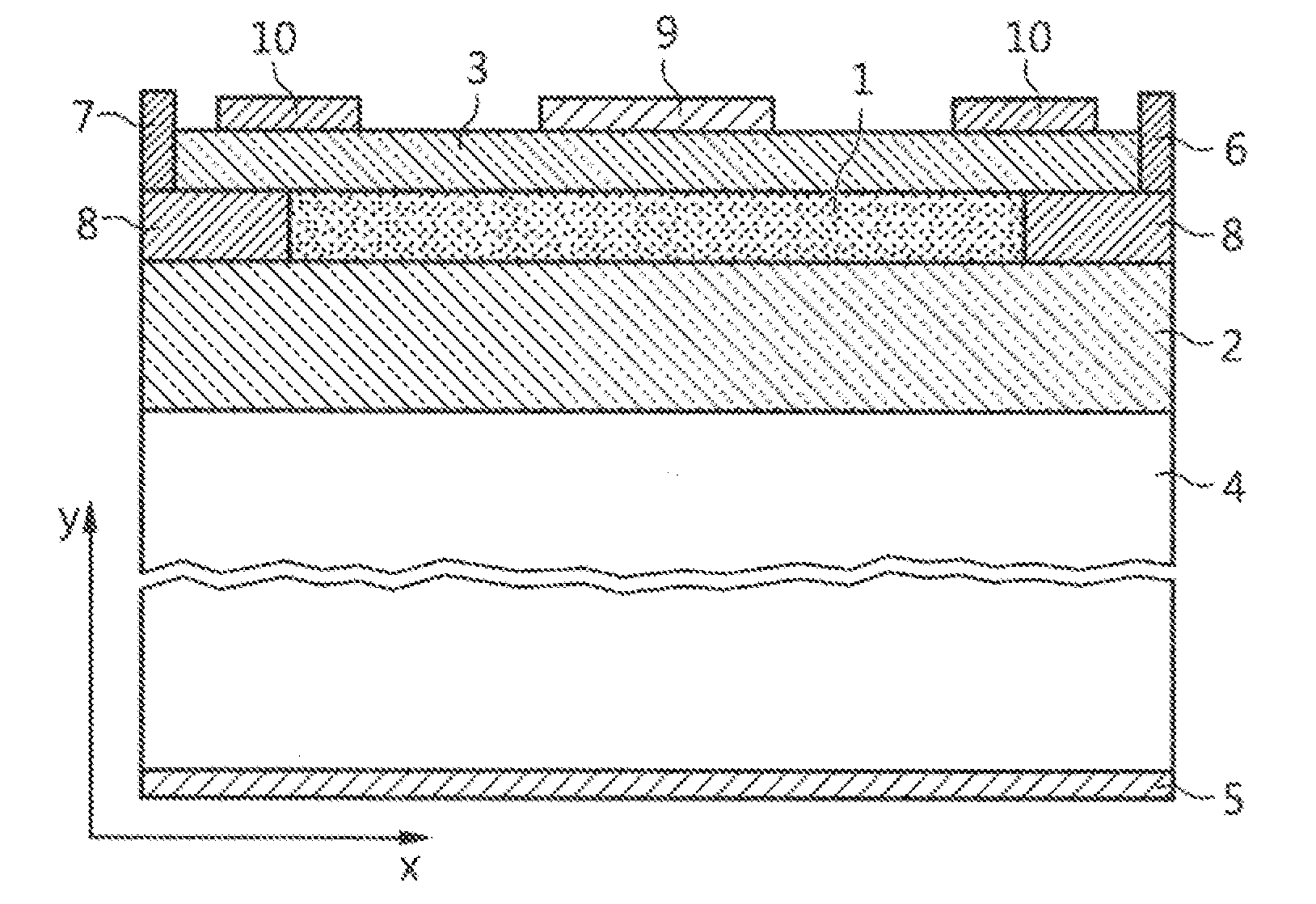
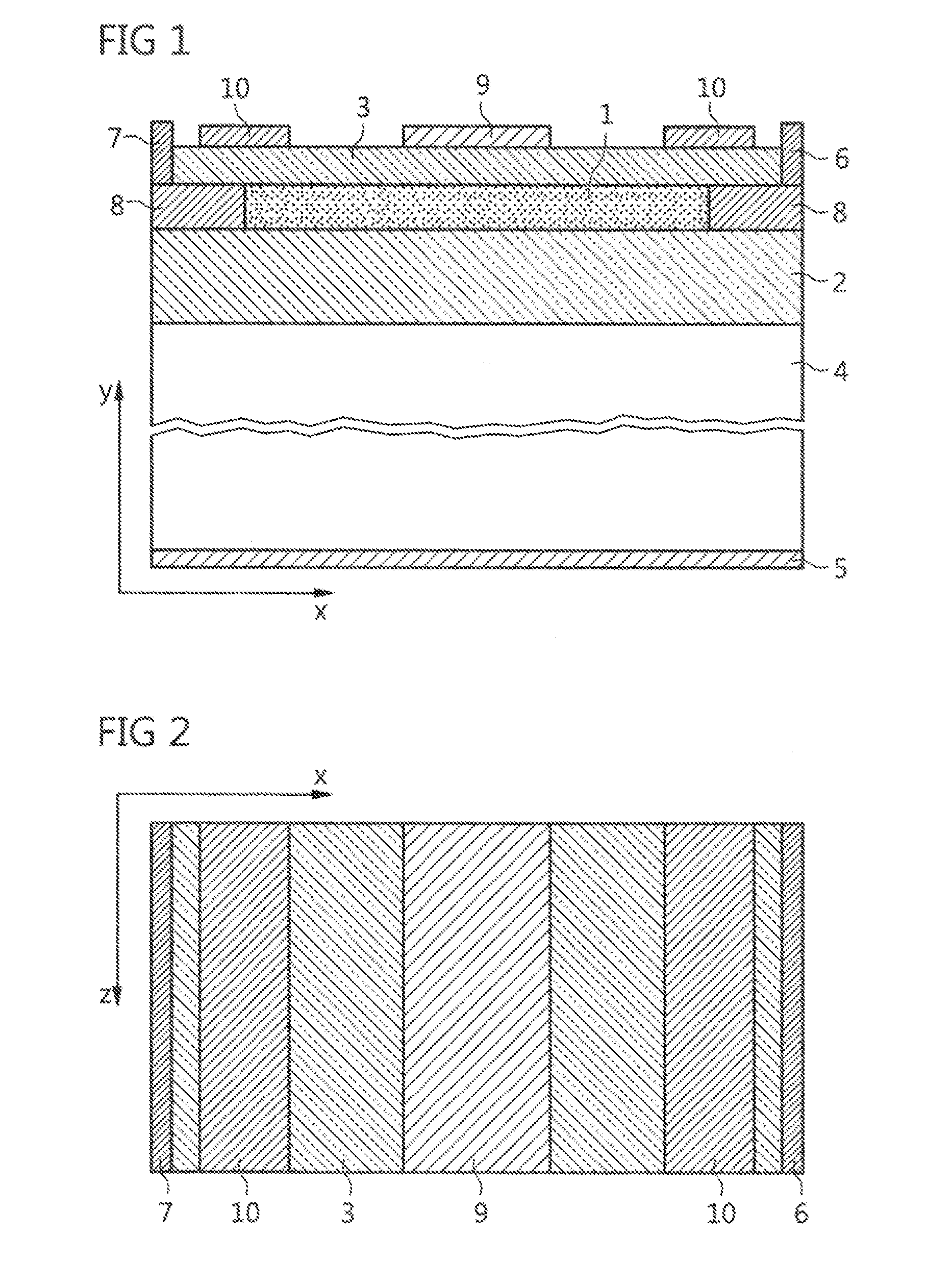
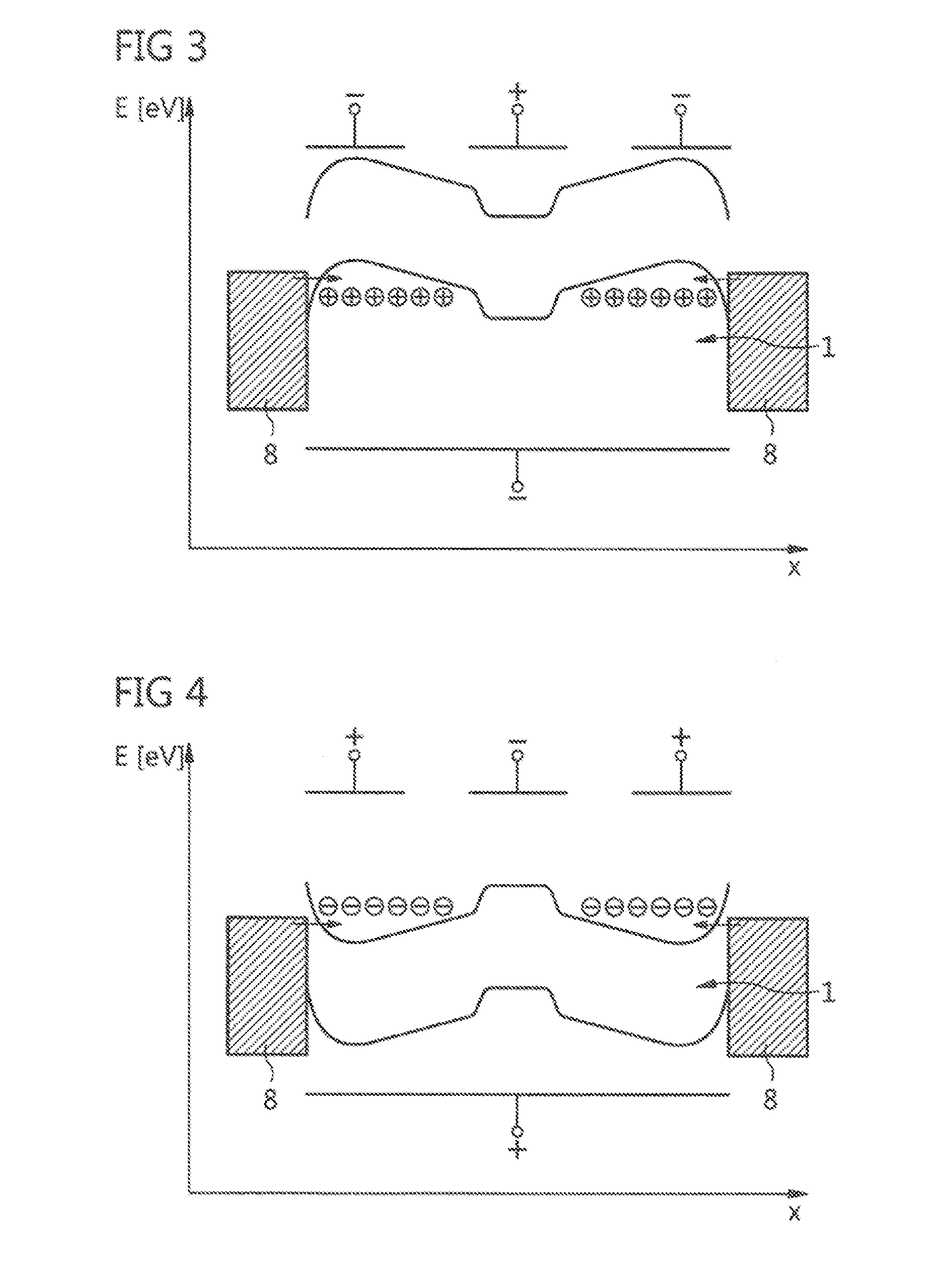
[0046]A field effect transistor arrangement schematically illustrated in FIGS. 1 and 2 has a planar channel layer 1 made of an undoped silicon material. The planar channel layer 1 is arranged on an upper side of an electrically insulating substrate layer 2, which consists of or comprises silicon oxide. The planar channel layer 1 is covered by an electrically insulating electrode insulation layer 3, which likewise consists of or comprises silicon oxide. Below substrate layer 2 a carrier substrate 4, and on the entire surface of the underside thereof, an electroconductively contactable adjusting electrode 5 are arranged.

[0047]On two opposite side edges of planar channel layer 1, an electroconductively contactable source electrode 6 and a drain electrode 7 are arranged, which protrude through electrode insulation layer 3, each into a contact region 8 that borders the planar channel layer laterally. Contact region 8 is embodied as a midgap Schottky barrier and is produced from nickel si...


PUM


Abstract

A field effect transistor arrangement having as planar channel layer comprises semiconductor material, the whole surface of the underside of the layer being applied to an upper side of an electrically insulating substrate layer and the upper side of the planar channel layer being covered by an insulation layer. The arrangement has a source electrode on a first side edge of the channel layer and a drain electrode on a second side edge of the channel layer and a control electrode arranged above the channel layer. An adjusting electrode is arranged on an underside of the substrate layer. A contact region between the source and drain electrodes and the planar channel layer is in each case configured as a midgap Schottky barrier. A respective barrier control electrode is arranged in the vicinity of the contact region of the source electrode and of the drain electrode, Each barrier control electrode can have a section that projects outwards in the direction of the planar channel layer.

Description

BACKGROUND AND SUMMARY[0001]The invention relates to a field effect transistor arrangement having a planar channel layer consisting of or comprising a semiconductor material, the whole surface of the underside of said layer being applied to an upper side of an electrically insulating substrate layer, and the upper side of said planar channel layer being covered by an electrically insulating electrode insulation layer, said arrangement also having a source electrode on a first side edge of the channel layer and a drain electrode on a second side edge of the channel layer, and having a control electrode arranged above the channel layer between the source electrode and the drain electrode.[0002]Field effect transistors form the basis for electronic circuits, such as those used in integrated circuits and / or microprocessors, for example. A very large number of field effect transistors are arranged within a space of a few square millimeters, and are contacted with one another in a suitabl...

Claims


Application Information

Patent Timeline
IPC IPC(8): H01L29/78H01L29/06H01L29/40
CPCH01L29/7838H01L29/0649H01L29/404H01L29/7839H01L29/78645H01L29/78648H01L29/78654
Inventor SCHWALKE, UDOWESSELY, FRANKKRAUSS, TILMANN
Owner TECH UNIV DARMSTADT
Learn More