
Power Electronics Housing And Packaging For Flywheel Energy Storage Systems

a technology of power electronics and energy storage systems, applied in the field of energy storage, can solve the problems of inability to meet the needs of power supply, inability to use active cooling methods and mechanisms, and large power supply

Active Publication Date: 2018-02-01
AMBER KINETICS
View PDF6 Cites 10 Cited by
  • Summary
  • Abstract
  • Description
  • Claims
  • Application Information

AI Technical Summary

Benefits of technology

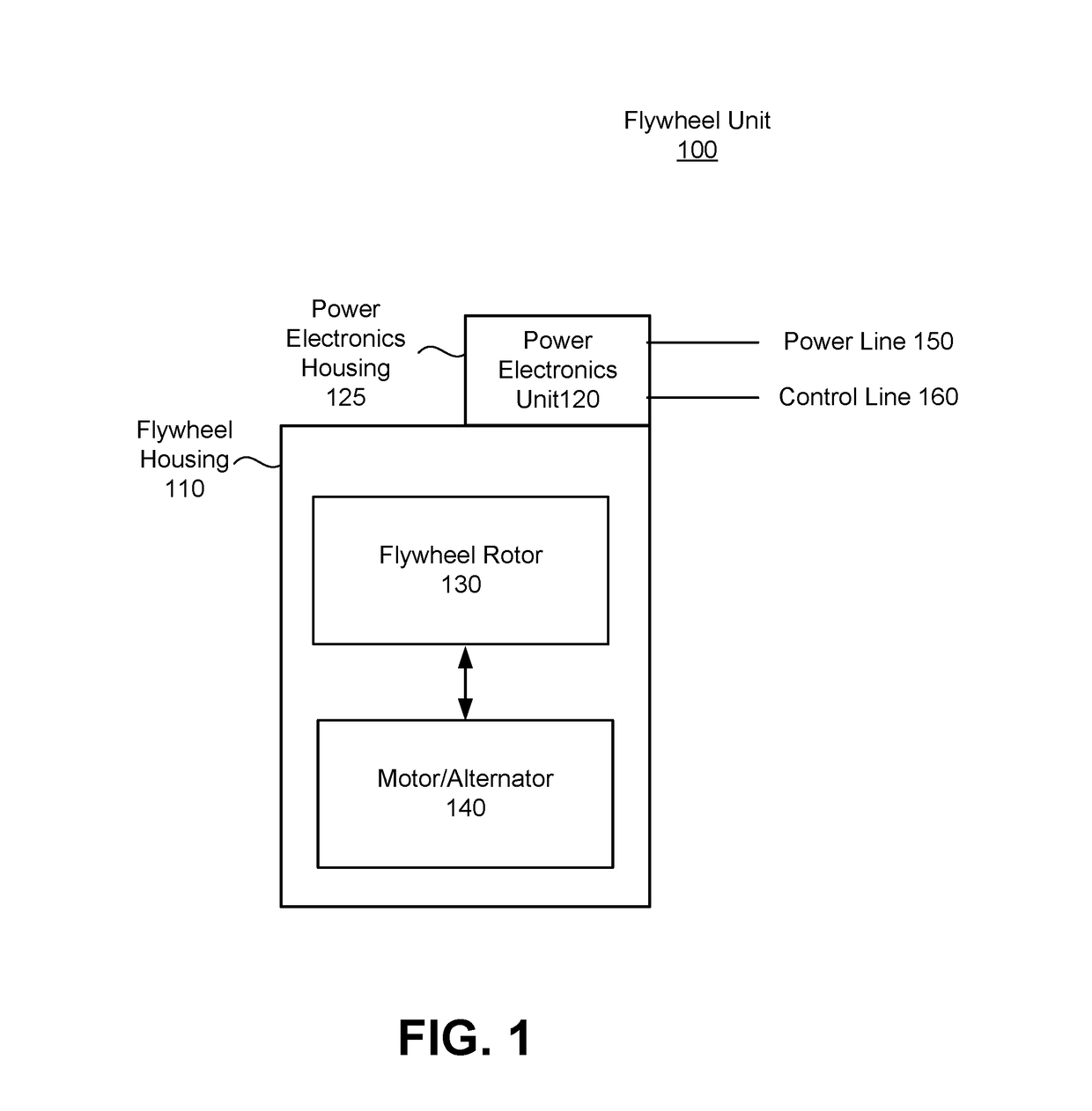
The patent describes a flywheel energy storage system that includes a rotating flywheel, a motor / alternator, and a power electronics unit. The power electronics unit is attached to the flywheel housing and includes one or more power electronic circuits. The system also has a heat source and a heat sink. The heat source generates heat, and the heat sink receives and transfers the heat to the external environment. The technical effects of the system include improved efficiency, reduced noise, and improved performance stability. The heat transferring system helps to maintain the proper temperature of the system components, which can improve the overall performance and reliability of the system.

Problems solved by technology

Many energy sources, particularly clean energy sources such as wind turbines and solar panels, generate energy that does not temporally match the load experienced.
However, despite the availability of such techniques, there are often instances where energy storage is important for meeting energy load.
Currently existing energy storage systems all have drawbacks of one form or another.
Such systems generally supply relatively large amounts of power for a relatively short duration of time.
Therefore, for purposes of cost and power efficiency (e.g., amount of power consumed relative to the amount of power stored), it is highly impractical to use active cooling methods and mechanisms in a flywheel energy storage system designed to store power over long periods.

Method used


Image

  • Power Electronics Housing And Packaging For Flywheel Energy Storage Systems
  • Power Electronics Housing And Packaging For Flywheel Energy Storage Systems
  • Power Electronics Housing And Packaging For Flywheel Energy Storage Systems

Examples


Embodiment Construction

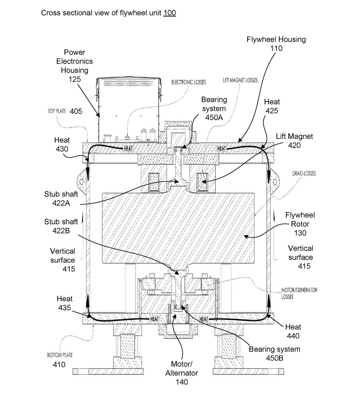
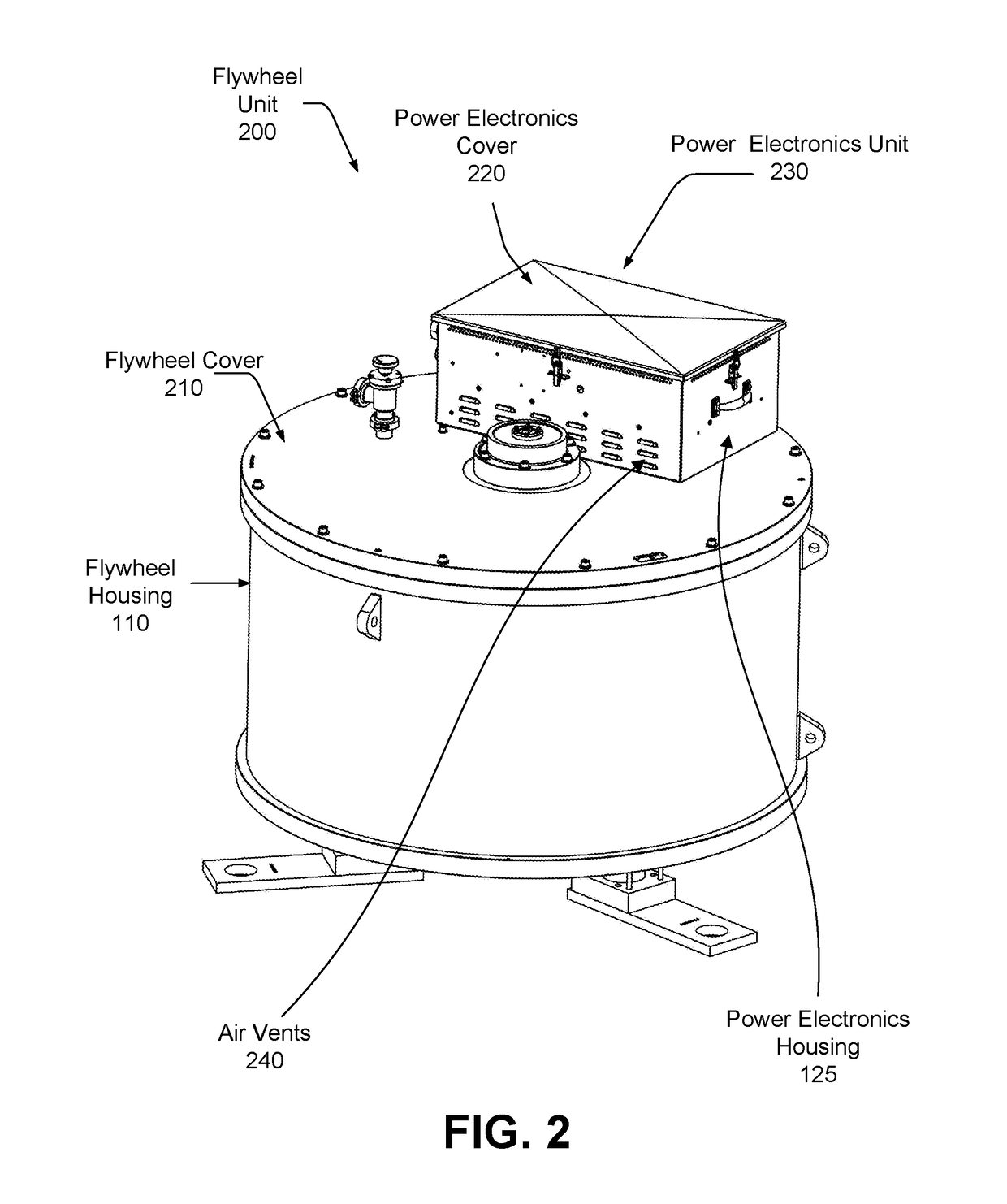
[0017]The present description relates to the packaging and housing of power electronics components performing operations such as power conversion, sensing, communications and status monitoring to drive an electric machine. For certain flywheel applications, it is advantageous to mount such power electronic components as closely as possible with a flywheel housing. Such an arrangement reduces high-frequency motor-drive cable lengths and avoids the accompanying electromagnetic challenges of co-located sensing and drive cabling.

[0018]The system can also be configured to make use of passive cooling for the power electronics components of a flywheel by mounting the power electronics components onto the housing of a flywheel unit. Mounting of the power electronics components directly on the flywheel housing permits sharing of a large thermal dissipation surface area of the flywheel housing. However, mounting the power electronics components to the flywheel housing of existing flywheel ene...


PUM


Abstract

A flywheel energy storage system includes a flywheel housing that encloses a flywheel rotor, a motor / alternator, and a power electronics unit. The power electronics unit includes a power electronics housing directly mounted on the flywheel housing, and one or more power electronic circuits enclosed by the power electronics housing. The direct mounting of the power electronics housing on the flywheel housing enables thermal distribution for passive cooling purposes. The design of the flywheel energy storage system also reduces the vibrational forces imparted by the power electronics housing on the flywheel housing.

Description

BACKGROUND1. Field of Art[0001]This description generally relates to energy storage, and particularly to energy storage using flywheels.2. Description of the Related Art[0002]Many energy sources, particularly clean energy sources such as wind turbines and solar panels, generate energy that does not temporally match the load experienced. In much of the developed world, energy generation follows experienced load, such that energy is provided as needed. Under circumstances of high load, techniques such as the use of peaker generators and spinning and non-spinning reserves on thermal generators allow for generation that matches high and variable load. However, despite the availability of such techniques, there are often instances where energy storage is important for meeting energy load.[0003]Currently existing energy storage systems all have drawbacks of one form or another. Size, price, storage efficiency, efficacy, and safety are all concerns when designing an energy storage system. ...

Claims


Application Information

Patent Timeline
Patent Type & Authority Applications(United States)
IPC IPC(8): H02K5/24H02K5/22H02K5/20H02K7/02
CPCH02K5/24H02K5/20H02K5/22H02K7/025Y02E60/16H02K5/207
Inventor HITCHCOCK, ROGER NELSONVASILNAK, PETERSENESKY, MATTHEW K.HOLLOWAY, MARK J.BAKHOLDIN, DANIELSANDERS, SETH R.
Owner AMBER KINETICS
Learn More