
Doherty Amplifier

a technology of amplifiers and amplifiers, applied in amplifiers, amplifier input/output impedence modifications, electrical apparatus, etc., can solve the problems of bottlenecks limiting the frequency over which amplifiers can be used, increase signal distortion, and reduce efficiency, so as to increase the operational bandwidth

Active Publication Date: 2018-02-01
AMPLEON NETHERLANDS
View PDF3 Cites 11 Cited by
  • Summary
  • Abstract
  • Description
  • Claims
  • Application Information

AI Technical Summary

Benefits of technology

The patent describes a type of amplifier called a Doherty amplifier that can match the impedance and phase of signals across a wider range of frequencies. This makes it easier for the amplifier to work at different frequencies. The result is a wider bandwidth of operation, which can be useful in RF communication systems that use multiple bands. Overall, this technology allows for better performance and reliability in RF communication systems.

Problems solved by technology

It is undesired to operate an amplifier past saturation because driving an amplifier in the non-linear region also increases distortion of the signal.
This means that when amplifying RF signals with high input power, conventional amplifiers cannot be used in the high-efficiency region, they have to be used in their linear region, where efficiency is much lower.
In two, three or four way Doherty amplifiers, the circuitry used to split the input signal and to combine the output signal such that the signals from the different amplifiers are phase and impedance matched causes a bottleneck that limits the frequencies over which the amplifier can be used.
Therefore, to cover the whole bandwidth, a large number of different amplifiers have to be implemented which is costly in time and resources and inefficient in power consumption.

Method used


Image

  • Doherty Amplifier
  • Doherty Amplifier
  • Doherty Amplifier

Examples


Embodiment Construction

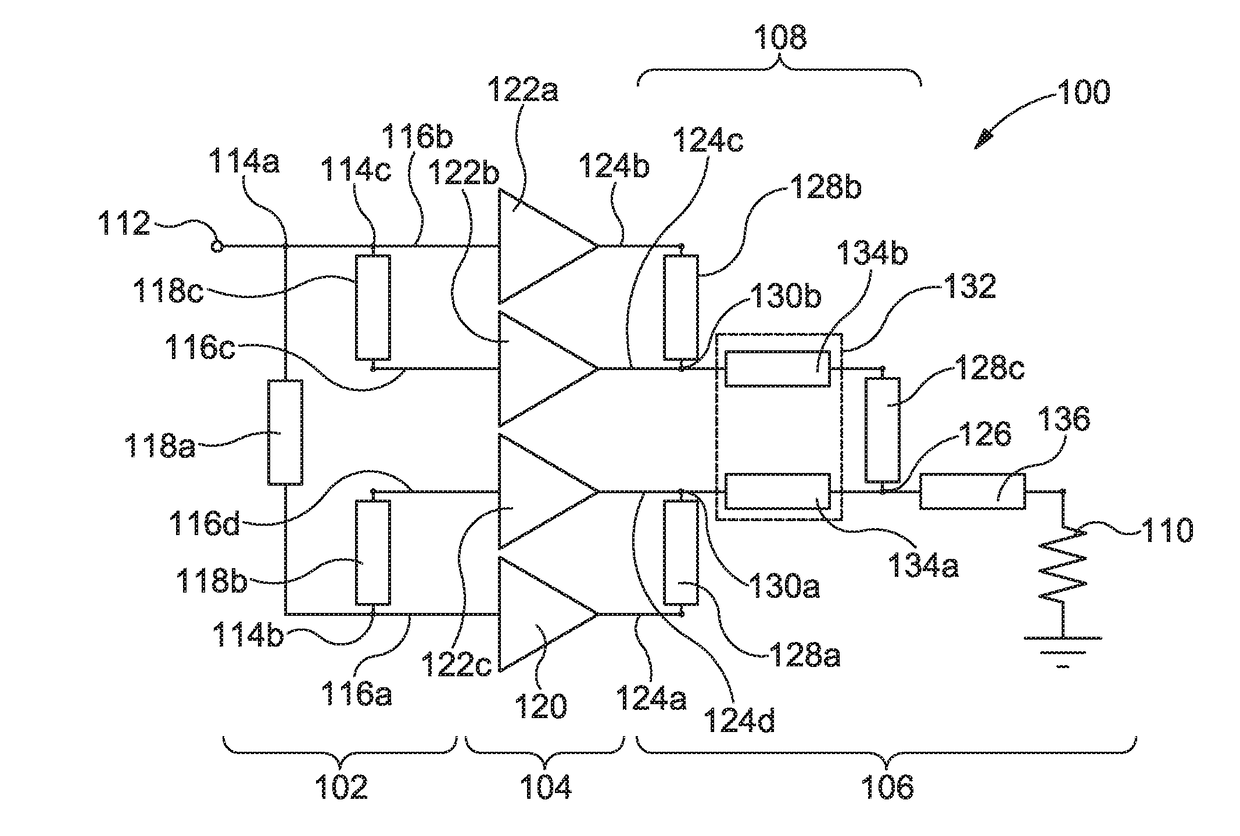
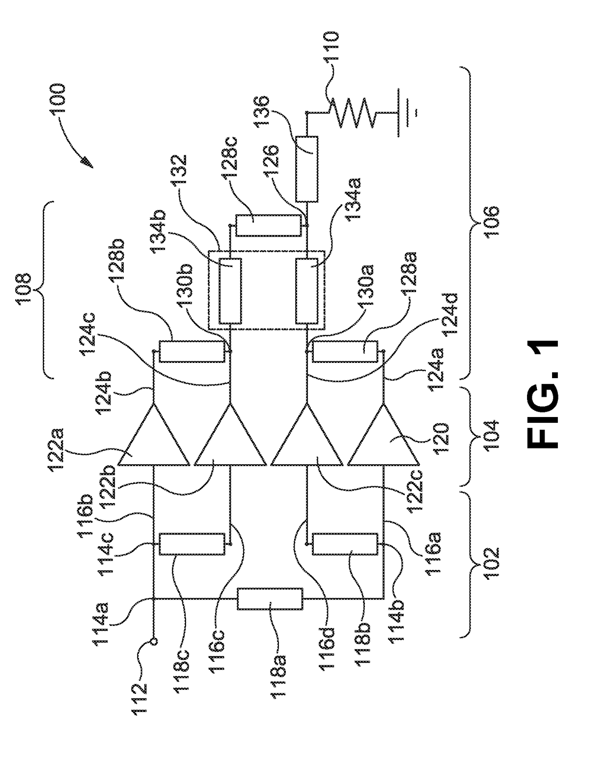
[0054]FIG. 1 shows an example of a four-way Doherty amplifier 100. The Doherty amplifier 100 includes an input stage 102, an amplifier stage 104, and an output stage 106.

[0055]The input stage 102 is configured to receive an RF input signal and to split the signal into separate parts, which are provided to the amplifier stage 104.

[0056]The amplifier stage 104 takes the separate signals and amplifies them to provide separate amplified signals.

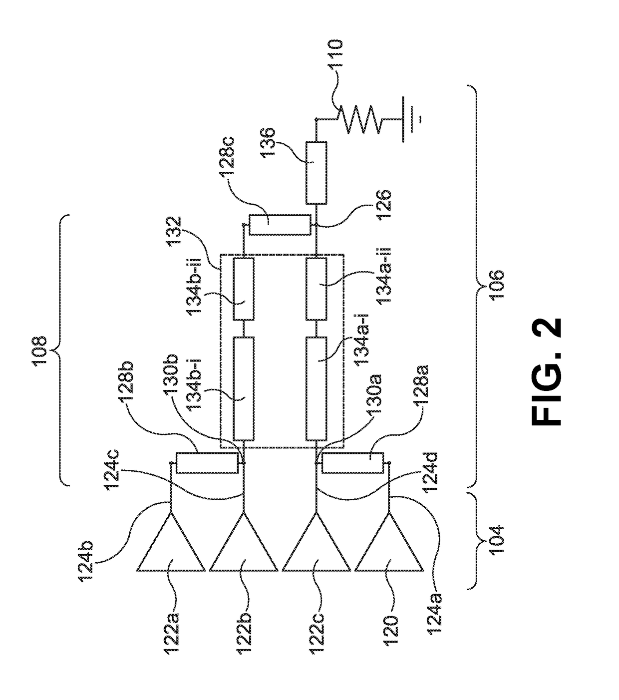
[0057]The output stage 106 includes combination circuitry 108 that is configured to recombine the separate signals to provide an amplified RF output signal. The output signal is provided to a load 110. The combination circuitry 108 is configured to impedance match the separate amplified signals to the output load 110.

[0058]The impedance matching introduces phase shifts into the separate amplified signals. However, it is also desirable for the separate signals to be phase matched when then they are combined and so corresponding phase shifts are in...


PUM


Abstract

Embodiments described herein relate to a Doherty amplifier. The Doherty amplifier may include a main amplifier and a first peak amplifier, a second peak amplifier, and a third peak amplifier, each amplifier having an input and an output. The Doherty amplifier may also include a combining network configured for combining signals emerging at outputs of the amplifiers. The signals are combined at a combining node. The combining network includes a first impedance inverter arranged in between the output of the main amplifier and the output of the third peak amplifier. The combining network also includes a second impedance inverter arranged in between the output of the first peak amplifier and the output of the second peak amplifier. The combining network also includes a first 180 degrees phase shifter and a second 180 degrees phase shifter. Additionally, the combining network includes a third impedance inverter.

Description

CROSS-REFERENCE TO RELATED APPLICATION[0001]The present application is a national stage entry of PCT / EP2016 / 052423 filed Feb. 4, 2016, which claims priority to EP 15153816.2 filed on Feb. 4, 2015, the contents of each of which are hereby incorporated by reference.FIELD OF THE DISCLOSURE[0002]The present disclosure relates to a Doherty Amplifier. In particular, but not exclusively, the present disclosure relates to a four-way Doherty amplifier that is capable of amplifying a signal over a wide operating bandwidth.BACKGROUND TO THE DISCLOSURE[0003]Modulated radio-frequency (RF) signals are used in a wide variety of communications systems such as mobile phones, cellular base stations for mobile phones and satellite communications. In these applications, it is necessary to amplify the RF signal.[0004]Conventional amplifiers have a generally linear relationship between input power and efficiency, and between input power and output power, during normal operation. As input power increases,...

Claims


Application Information

Patent Timeline
IPC IPC(8): H03F1/02H03F3/60H03F3/213H03F1/56H03F3/195
CPCH03F1/0288H03F1/56H03F3/195H03F3/213H03F3/604H03F2200/423H03F2200/451H03F1/565H03F3/245H03F2200/387
Inventor MORONVAL, XAVIER BRUNO JEAN
Owner AMPLEON NETHERLANDS
Learn More