Suppressed upper receiver group having locking suppressor with through brake

a technology of suppressor and upper receiver, which is applied in the field of suppressor and suppressor with through brake, can solve the problems of difficult and time-consuming removal of residue buildup, and the suppression of the optimum operational characteristics, so as to reduce the discharge of propellant gas, prevent excessive back pressure, and reduce the effect of pressure conditions

Inactive Publication Date: 2018-02-08
LARUE MARK C
View PDF0 Cites 32 Cited by
  • Summary
  • Abstract
  • Description
  • Claims
  • Application Information

AI Technical Summary

Benefits of technology

[0011]The suppressor device is designed to divide the propellant charge from cartridge firing into primary and secondary flow paths to ensure low pressure conditions and prevent excessive back pressure or blow-back to the bore of the firearm barrel. This feature minimizes propellant gas discharge from the cartridge chamber of the barrel toward the shooter as the spent cartridge case is unseated. This feature also ensures that the spent cartridge cases, typically referred to as “brass” are quite clean, i.e., quite free of gunpowder residue, when extracted and ejected.
[0012]The suppressor mounting adapter includes a propellant gas processing geometry and projects through the suppressor housing, with an integral front flash hider end thereof projecting through a central opening in the forward closure wall of the suppressor housing. The gas processing suppressor mounting adapter ensures minimal buildup of propellant residue within the suppressor housing so that internal cleaning of the suppressor is required with much less frequency.
[0013]For e

Problems solved by technology

Hot propellant gas striking the baffles and other components within a surpressor housing typically creates significant problems which until the present time there has been no reasonable solution.
In a relatively short period of time the buildup of propellant residue will cause the suppressor to begin to lose its optimum operational chara

Method used


Image

  • Suppressed upper receiver group having locking suppressor with through brake
  • Suppressed upper receiver group having locking suppressor with through brake
  • Suppressed upper receiver group having locking suppressor with through brake

Examples


Embodiment Construction

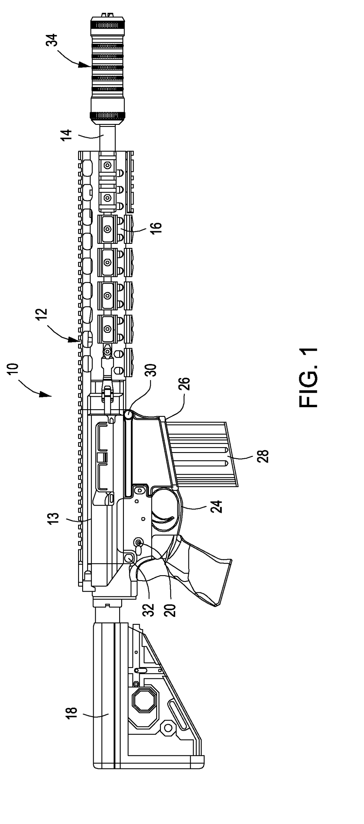
[0030]Referring now to the drawings and first to the side elevation view of FIG. 1, a tactical firearm constructed according to the principles of the present invention is shown generally at 10 and is of the character identified as an M-4, M-16 or AR-15 auto-loading rifle. The M-4 and M-16 rifles are typically utilized by military and law enforcement personnel and have settings for semi-automatic fire, where the trigger of the rifle is pulled for discharge of individual rounds of ammunition and full automatic fire, where the rifle will continuously fire round after round as long as the trigger remains pulled. AR-15 tactical rifles are typically provided with a non-adjustable setting that limits the rifle to semi-automatic fire. AR-15 rifles are widely used by sportsmen for target shooting, hunting and a wide range of general shooting activities.

[0031]The firearm 10 has a barrel cartridge or upper receiver group shown generally at 12 in FIG. 1 is generally defined by an upper receiver...


PUM


Abstract

A suppressed upper receiver group for a firearm having a suppressor mounted to the barrel thereof. The suppressor has a tubular housing defining primary and secondary flow paths for propellant gas processing, diverting a portion of the propellant gas to the secondary flow path for pressure control. A number of baffle members are arranged in spaced relation within the housing and define serially arranged propellant gas processing chambers. A suppressor mounting adapter is connected with the barrel and has a propellant gas processing section having a propellant flow bore and extends completely through the housing and has a flash retarding tip projecting through a discharge opening of the housing.

Description

BACKGROUND OF THE INVENTIONField of the Invention[0001]The present invention generally concerns firearms, such as rifles, and more particularly concerns sound and flash suppressors that are mounted by threading a generally cylindrical suppressor device onto the threaded end of the barrel of a firearm. More particularly, the present invention concerns a suppressed upper receiver group including an upper receiver mechanism and cartridge gas energized auto-loading mechanism and a barrel for a tactical rifle wherein a sound and flash suppressor device is provided at the forward end or muzzle of the barrel. Even more specifically the present invention concerns a sound and flash suppressor having a generally cylindrical suppressor body or housing having a muzzle brake device that extends completely through the tubular body of the suppressor body and is designed to substantially eliminate baffle strikes by hot gunpowder residue and thus significantly minimize the need for frequent cleaning...

Claims


Application Information

Patent Timeline
IPC IPC(8): F41A3/66F41A21/34F41A21/32F41A21/30
CPCF41A3/66F41A21/325F41A21/34F41A21/30
Inventor LARUE, MARK C.
Owner LARUE MARK C
Why Eureka
Try Eureka