
High Voltage Insulating Electric Tool

a high-voltage insulating and electric tool technology, applied in the field of electric tools, can solve the problems of affecting the use of tools, and affecting the use of tools, and achieve the effect of strong resistance and chemical stability

Inactive Publication Date: 2018-02-15
TALENT KEY HLDG
View PDF5 Cites 3 Cited by
  • Summary
  • Abstract
  • Description
  • Claims
  • Application Information

AI Technical Summary

Benefits of technology

This patent is about a new electric tool that can be easily replaced after wear and used in high-volage environments. The tool has a ceramic insulating fitting that prevents electric shock and can be easily replaced if needed. The ceramic cutting edges are replaceable, which avoids scrapping the entire tool due to damage. Ceramic and plastic materials are stable, resistant to chemicals, and have self-lubrication properties that prevent rusting and static current during use.

Problems solved by technology

After the plastic sheath has been used for a period of time, it may be cracked and damaged due to wear and tear, resulting in failure of insulation.
After metallic cutting edges have been used for a period of time, problems such as serious burst of the cutting edges, blunting of the cutting edges and large clearance between the cutting edges will be emerged.
As the cutting edges and the bodies are integrally assembled, the cutting edges cannot be ground again and cutting, peeling and other use functions will be lost after wear.
Electric tools made of metallic material are liable to corrosion in the air.
Although surface treatment may be adopted in the later stage to resist corrosion, the cost will be increased remarkably.
The oxidized electric tools are even more unsuitable for this occasion.
In addition, if electric tools completely made of plastic are used on an occasion of high / low frequency circuit, they will be worn fast.
Frequent replacement of the tools will lead to increase of maintenance cost.
Therefore, based on the defects of prior art and people's need for use of insulating tools in a high voltage environment, it is in urgent need of a new type of electric tool, which is not only replaceable after wear but also usable in an environment of high voltage, without worries of breakdown.

Method used


Image

  • High Voltage Insulating Electric Tool
  • High Voltage Insulating Electric Tool
  • High Voltage Insulating Electric Tool

Examples


Embodiment Construction

[0024]The term “insulating electric tools” herein includes all relevant electric tools used during operation in high-low voltage and high-low frequency environment. For example, the relevant electric tools include insulating pliers, insulating screwdrivers and other electric tools.

[0025]The high voltage insulating electric tool of the present invention comprises an insulating handle made of plastic material and an insulating fitting made of ceramic material. The insulating fitting is mounted on the insulating handle in a replaceable manner to directly contact a work piece under service condition and prevent the risk of electric shock.

[0026]Preferably, the plastic material is selected form the group consisting of PE, PP, PVC or PET. Obviously, those skilled in the art should understand that the plastic material may also be any other insulating plastic materials. In an embodiment of the invention, the ceramic material mainly includes zirconium oxide.

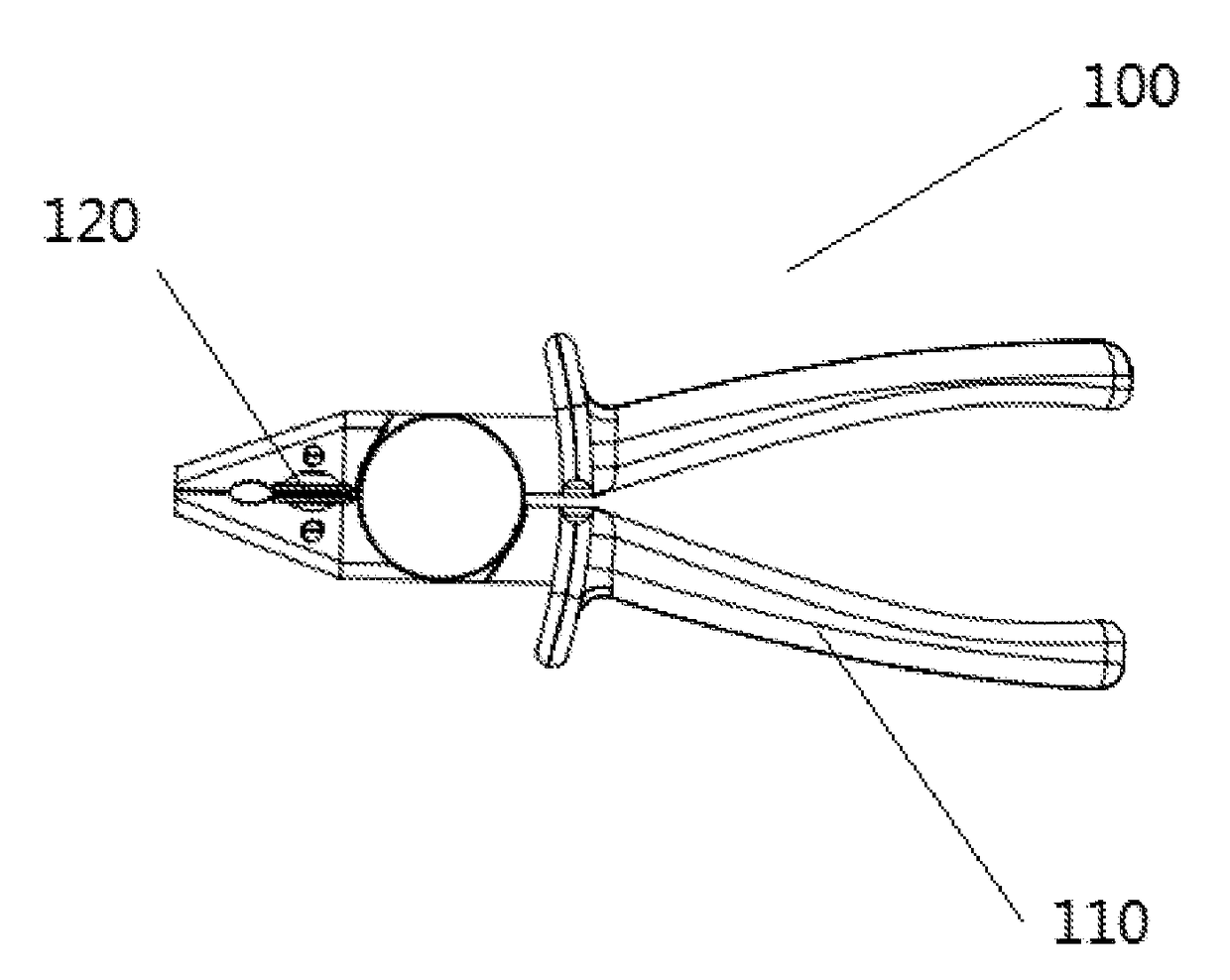
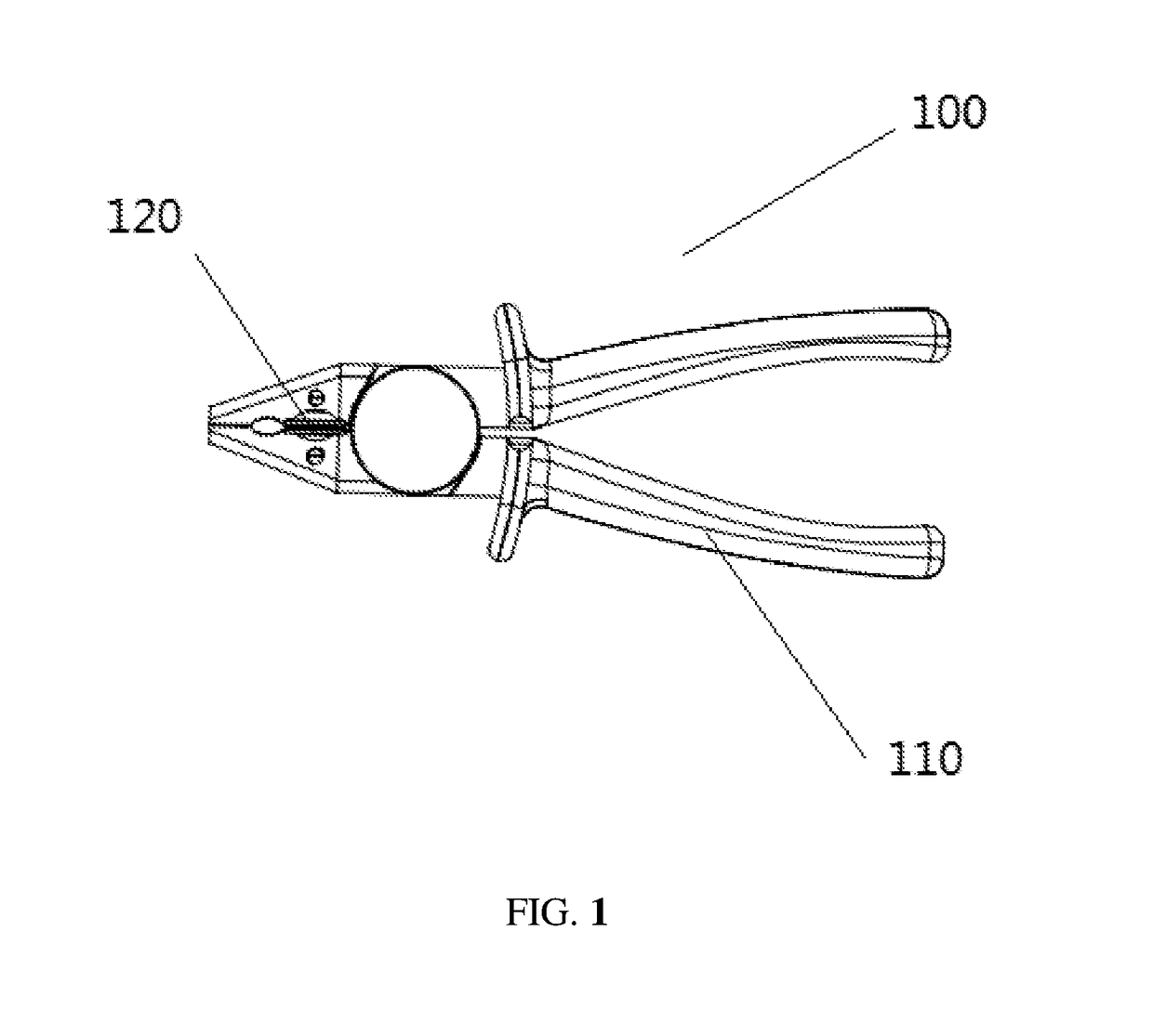
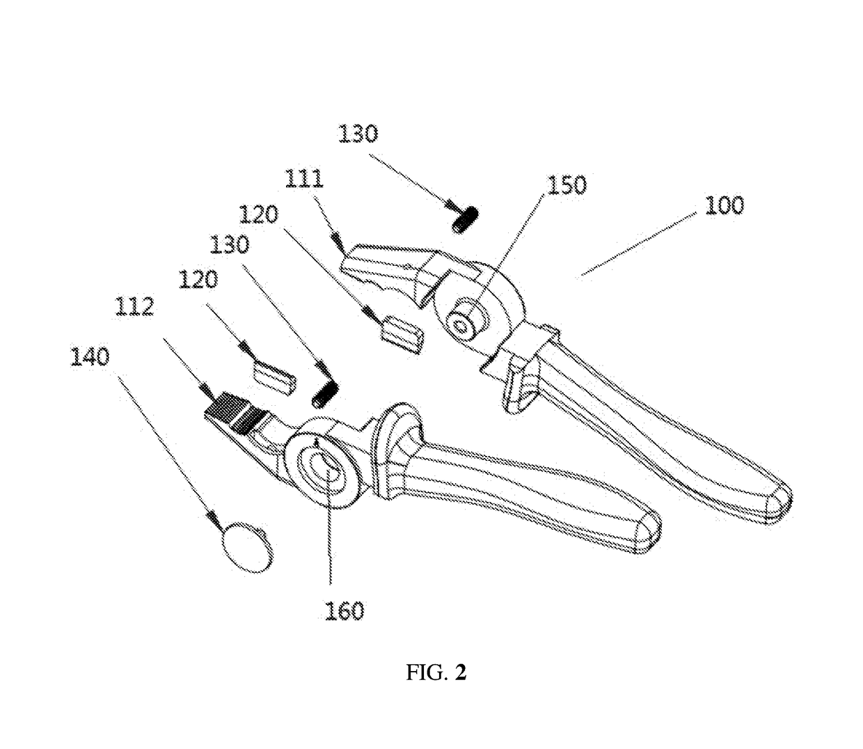
[0027]As shown in FIG. 1 and FIG. 2...


PUM


Abstract

The present invention discloses a high voltage insulating electric tool, comprising insulating handles made of plastic material, and insulating fittings made of ceramic material. The insulating fittings are mounted on the insulating handles in a replaceable manner to directly contact a work piece under service condition and prevent electric shock. The present invention adopts handles made of plastic material and cutting edges made of ceramic so that the entire product cannot bear a risk of breakdown by current in an environment of high voltage. The ceramic cutting edges made of ceramic are replaceable, thereby avoiding the circumstance that the entire metallic electric tool has to be scrapped due to burst, blunting or large clearance of the cutting edges. Further, plastic material and ceramic have desirable chemical stability and strong resistance to acids, alkalis and other chemicals.

Description

CROSS REFERENCE TO RELATED APPLICATIONS[0001]The present application claims the benefit of Chinese Patent Application No. 201620870405.5 filed on Aug. 12, 2016. All the above are hereby incorporated by reference.TECHNICAL FIELD OF THE INVENTION[0002]The present invention relates to an electric tool, more particularly, to an electric tool that can be used in a high voltage environment and bear the features of replaceable fittings and no breakdown by high voltage.BACKGROUND OF THE INVENTION[0003]Most operation tools are metallic tools externally covered with plastic as insulation, and their voltage insulation is not higher than 500V in general. After the plastic sheath has been used for a period of time, it may be cracked and damaged due to wear and tear, resulting in failure of insulation.[0004]After metallic cutting edges have been used for a period of time, problems such as serious burst of the cutting edges, blunting of the cutting edges and large clearance between the cutting edg...

Claims


Application Information

Patent Timeline
Patent Type & Authority Applications(United States)
IPC IPC(8): B25G1/12B25B15/02B25F1/00
CPCB25G1/12B25B15/02B25F1/003B25G1/125B25B7/08
Inventor SZE, WAI PO
Owner TALENT KEY HLDG
Learn More