
Image receiving sheet

a technology of image receiving sheet and toner image, which is applied in the direction of cellulosic plastic layered products, instruments, synthetic resin layered products, etc., can solve the problems of small fixing power of electrophotographic image formed on electrophotographic image receiving sheet, peeling, and decrease in accumulation properties, so as to achieve excellent fixing properties and suppress bonding between stacked sheets

Inactive Publication Date: 2018-02-15
FUJIFILM CORP
View PDF7 Cites 1 Cited by
  • Summary
  • Abstract
  • Description
  • Claims
  • Application Information

AI Technical Summary

Benefits of technology

The present invention provides an image-receiving sheet that has excellent properties for fixing images during high-speed printing. Additionally, the sheet helps prevent bonding between stacked sheets.

Problems solved by technology

Particularly, in a case where electrophotographic printing is performed at high speed, there have been problems in that the fixing power of a toner image formed on the electrophotographic image receiving sheet is small, and the electrophotographic image receiving sheets discharged from the printing machine and stacked are bonded together and are hard to peel off.
Even in the case of performing high speed printing by the ink jet method, ink jet image receiving sheets discharged from the printing machine and stacked are bonded to each other and are hard to peel off in some cases.
For example, it is considered that the cause of the decrease in the accumulation properties in electrophotographic printing is that the charge amount due to high speed transportation is increased and the bonding due to static electricity becomes strong.
Therefore, for example, even in a case where an image receiving layer is formed on a transparent support, the image receiving sheet becomes unsuitable for the purpose of OHP.

Method used


Image

  • Image receiving sheet
  • Image receiving sheet
  • Image receiving sheet

Examples


example 1

[0388]Coating solutions having the following compositions were prepared for forming respective layers.

[Coating solution for forming image receiving layer]Water420parts by massPolyolefin emulsion (ARROWBASE (registered trademark) SE1013N, Unitika Ltd.,268parts by masssolid content: 20 mass %)Acryl emulsion (AQUABRID (registered trademark) AS563, Daicell Finechem Ltd.,140parts by masssolid content: 28 mass %)Oxazoline crosslinking agent (EPOCROS (registered trademark) WS700, Nippon168parts by massShokubai Co., Ltd., solid content: 25 mass %)Surfactant (sodium = 1.2-{bis(3,3,4,4,5,5,6,6,6-nanofluorohexylcarbonyl)}4.3parts by massethanesulfonate, solid content: 2 mass %)[Coating solution for forming antistatic layer]Water491parts by massPolyolefin emulsion (ARROWBASE (registered trademark) SE1013N, Unitika Ltd.,169parts by masssolid content: 20 mass %)Acryl emulsion (AQUABRID (registered trademark) AS563, Daicell Finechem Ltd.,30parts by masssolid content: 28 mass %)Oxazoline crosslinki...

example 2

[0399]An image receiving sheet was completed in the same manner as in Example 1 except for causing the solid content concentration of the coating solution for forming the image receiving layer in Example 1 to be two times.

example 3

[0400]An image receiving sheet was completed in the same manner as in Example 1 except for causing a coating amount of the coating solution for forming the image receiving layer in Example 1 to be 17 mL / m2.


PUM

PropertyMeasurementUnit
thicknessaaaaaaaaaa
thicknessaaaaaaaaaa
thicknessaaaaaaaaaa

Abstract

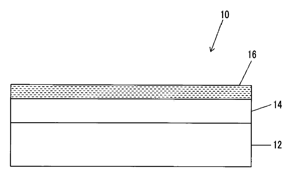
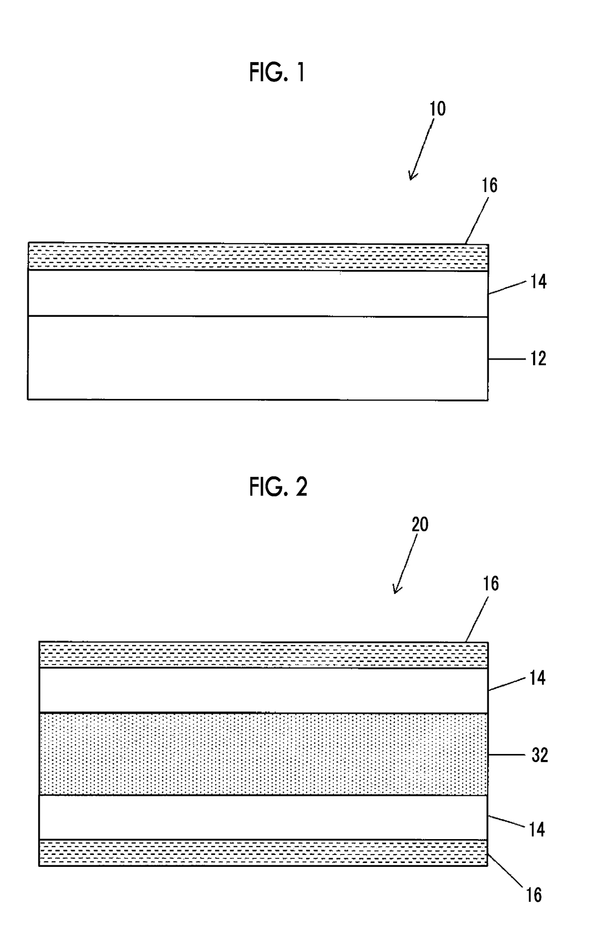
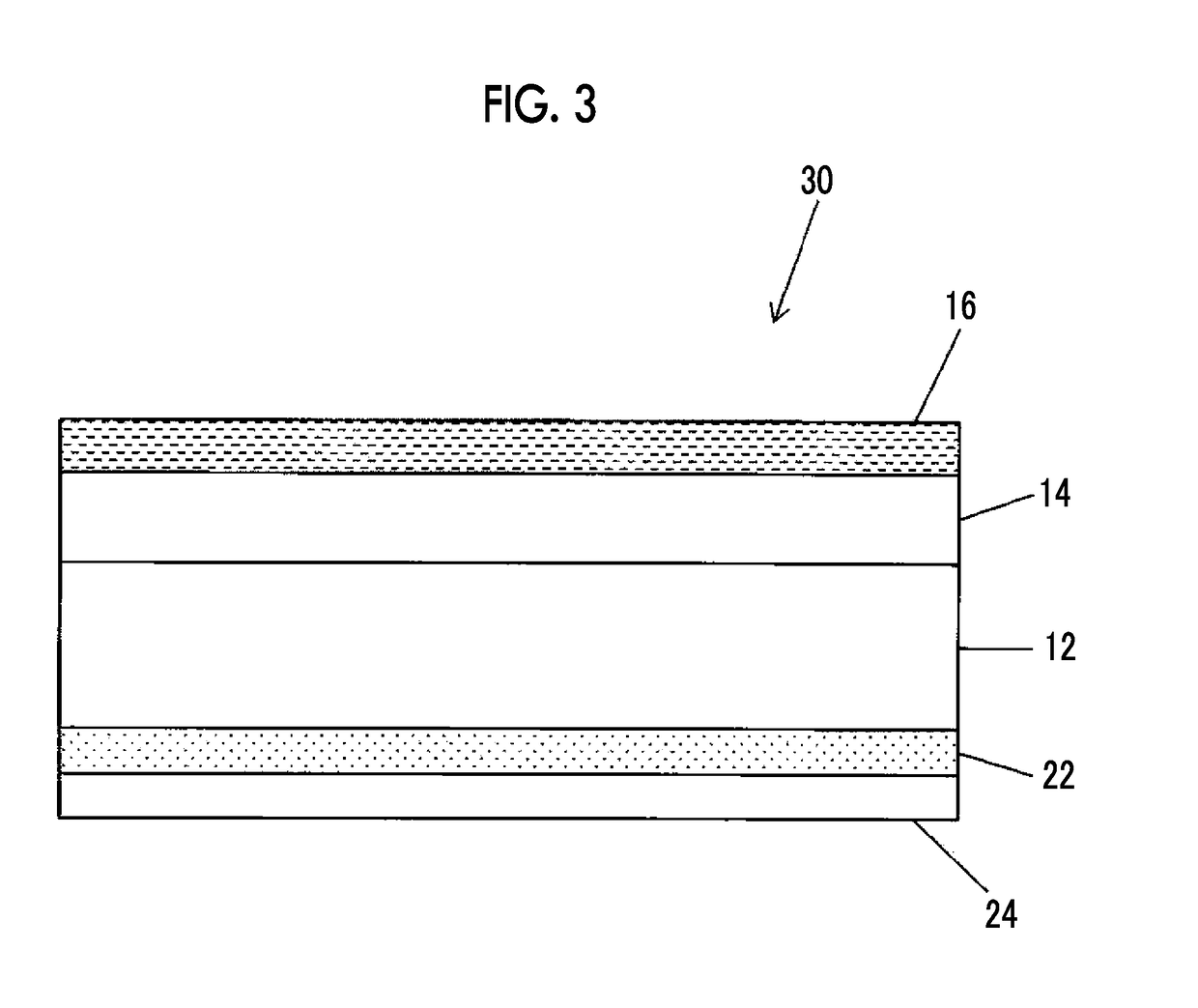
An image receiving sheet includes an image receiving layer including a resin and having a thickness of 1 μm or greater; and an antistatic layer being the outermost layer, including a resin and at least one conductive material selected from conductive particles and a conductive polymer and having a thickness smaller than that of the image receiving layer, on at least one surface of a support, in an order from the support side.

Description

CROSS-REFERENCE TO RELATED APPLICATIONS[0001]This application is a continuation application of International Application No. PCT / JP2016 / 066476, filed Jun. 2, 2016, the disclosure of which is incorporated herein by reference in its entirety. Further, this application claims priority from Japanese Patent Application No. 2015-112629, filed Jun. 2, 2015, the disclosure of which is incorporated herein by reference in its entirety.BACKGROUND OF THE INVENTION1. Field of the Invention[0002]The present invention relates to an image receiving sheet.2. Description of the Related Art[0003]In recent years, according to the spread of electrophotographic copying machines and various printers, a full color image with high quality is widely obtained by forming an image on an image receiving sheet (hereinafter, also simply referred to as “image receiving sheet” or “sheet” in some cases) such as coated paper and transparent film coated with an image receiving layer including a resin.[0004]For example,...

Claims


Application Information

Patent Timeline
Patent Type & Authority Applications(United States)
IPC IPC(8): B41M5/52G03G7/00
CPCB41M5/52G03G7/0026B32B27/32B32B27/36B41M5/502B41M5/506B41M5/5218B41M5/5227B41M5/5254B41M5/5272B41M5/5281G03G7/004G03G7/0046G03G7/0053G03G7/008B32B27/10B32B27/12B32B27/08B32B27/365B32B27/34B32B27/16B32B27/18B32B27/285B32B27/286B32B27/281B32B23/08B32B2255/28B32B2255/205B32B2255/24B32B2255/26B32B2255/10B32B2264/102B32B2264/104B32B2307/4026B32B2307/546B32B2307/306B32B2307/732B32B2307/412B32B2307/516B32B2307/518B32B2307/20G03G7/0086H01B1/02G03G7/00
Inventor TESHIMA, YUKIMIYAKE, KAZUHITO
Owner FUJIFILM CORP
Learn More