Single device for gas and flame detection, imaging and measurement, and drift correction method thereof

Active Publication Date: 2018-02-15
C I SYST ISRAEL
View PDF1 Cites 7 Cited by
  • Summary
  • Abstract
  • Description
  • Claims
  • Application Information

AI Technical Summary

Benefits of technology

[0011]The detection, imaging and measurement of hydrocarbon gas clouds and flames with the same device has a definite cost advantage over other methods using dedicated infrared imagers for each of the two types of events. This solution requires fewer instruments, fewer installations, and less maintenance, and therefore reduced costs. Infrared radiation imaging and measurement technology combined in a single device is a suitable candidate for such an endeavor, since both hydrocarbon gases an

Problems solved by technology

Explosions may cause fires, thus there is inherent danger from both the explosion itself and from the consequent ensuing fires.
In addition, fires may result from a plethora of diverse causes, and when occurring in such plants, such fires may themselves cause explosions.
The dangers are to both personnel and equipment, and the resulting damages may be in the worst cases loss of human lives and large financial losses to the owners of the plants.
Additionally, the release of the gases in question has a negative impact on the environment.
A gas detector of this type can easily miss the target gas if the gas cloud is present but does not physically meet the position of the detector (or path in case of cloud movement).
Therefore, the monitor cannot provide the necessary information on the location and size of the fire.
Current industry instrumentation does not allow for the detection, identification, and location of the concentration, size and prognosis information of explosive gas or vapor clouds and flames due to incipient fires.
Accordingly, current instrumentation cannot meet the additional requirements of being operable from a distance, in harsh environments, usually outdoors, and with minimal false alarms due to signals from other possible infrared sources, such as sun reflections, welding arcs, halogen lamps etc.
If this radiation

Method used


Image

  • Single device for gas and flame detection, imaging and measurement, and drift correction method thereof
  • Single device for gas and flame detection, imaging and measurement, and drift correction method thereof
  • Single device for gas and flame detection, imaging and measurement, and drift correction method thereof

Examples


Embodiment Construction

[0106]The principles and operation of the device according to the present invention may be better understood with reference to the drawings and the accompanying description.

[0107]Before explaining at least one embodiment of the invention in detail, it is to be understood that the invention is not necessarily limited in its application to the details of construction and the arrangement of the components and / or methods set forth in the following description and / or illustrated in the drawings and / or the examples. The invention is capable of other embodiments or of being practiced or carried out in various ways.

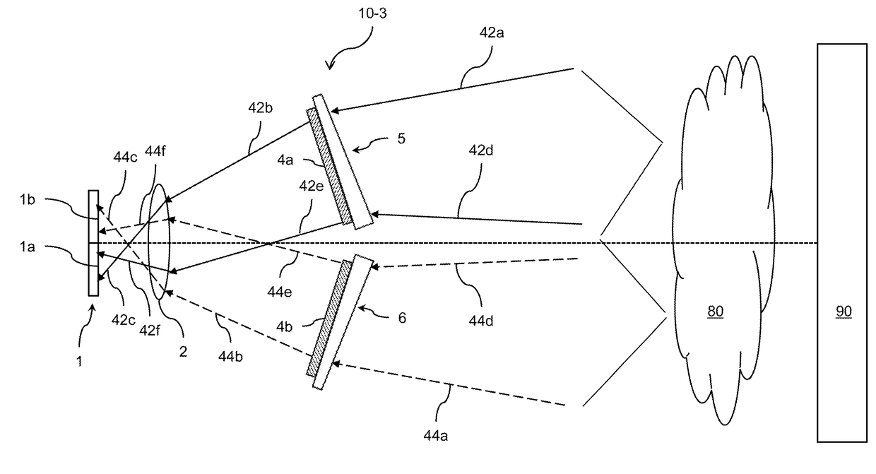
[0108]The present invention is a device for detecting and imaging both a cloud of hydrocarbon gas and / or a flame of burning material. The device performs the detection and imaging from a distance and can distinguish between the two types of events (i.e. hydrocarbon gas and flame of burning material). The device also corrects for signal drift resulting from the changing environmen...


PUM


Abstract

Devices image radiation from a scene that includes two materials with spectral characteristics in two different wavelength regions. A lens forms an image of the scene on a detector that includes an array of elements. A filtering arrangement integrated with the detector allows half of the detector elements to detect radiation in one of the wavelength regions and the other half of the detector elements to detect radiation in the other wavelength region. Each detector element can be constructed from two different sub-elements that are sensitive to radiation in one of the respective wavelength regions. A blackbody source positioned within the devices reduces drift induced by changes to the environment surrounding the devices. The blackbody source projects radiation onto a region of the detector that does not receive radiation from the scene. Pixel signals produced from the scene radiation are modified based on pixel signals produced from the blackbody.

Description

CROSS-REFERENCE TO RELATED APPLICATIONS[0001]This application is a Continuation-in-part of U.S. patent application Ser. No. 14 / 983,570, filed on Dec. 30, 2015. This application claims priority from U.S. Provisional Patent Application No. 62 / 135,183, filed Mar. 19, 2015, whose disclosure is incorporated by reference herein. This application is related to U.S. patent application Ser. No. 14 / 949,906 and U.S. patent application Ser. No. 14 / 949,909, both filed on Nov. 24, 2015, both of the disclosures of which are incorporated by reference in their entirety herein.TECHNICAL FIELD[0002]The present invention relates to the detection, imaging and measurement of infrared radiation.BACKGROUND OF THE INVENTION[0003]Industrial plants dealing with mining, production or storage of explosive or flammable gases and vapors such as hydrocarbons (methane, ethane, etc.), fuels of different kinds, hydrogen, acetylene, etc. are in constant danger of accidents. Explosions may cause fires, thus there is in...

Claims


Application Information

Patent Timeline
IPC IPC(8): G01J3/28G01N21/3504G01J3/02
CPCG01J3/2823G01J3/2803G01J3/0205G01N21/3504G01N2201/12G01J3/36
Inventor CABIB, DARIOGIL, AMIRLAVI, MOSHESINGHER, LIVIU
Owner C I SYST ISRAEL
Why Eureka
Try Eureka