Supercharge Your Innovation With Domain-Expert AI Agents!

Pressure Reducing Valve and A Pressure Reducing System

a pressure reducing valve and pressure reducing technology, applied in the direction of fluid pressure control, process and machine control, instruments, etc., can solve the problems of vaporized liquid to recover, bubble burst, energy released to produce cavitation phenomenon, etc., to achieve low cost, less high pressure leakage point, and high cost

Inactive Publication Date: 2018-02-15
BEIJING HUASHI UNITED ENERGY TECH & DEV
View PDF0 Cites 3 Cited by
  • Summary
  • Abstract
  • Description
  • Claims
  • Application Information

AI Technical Summary

Benefits of technology

The present invention aims to provide a pressure reducing valve that has fewer high pressure leakage points, occupies a smaller space, and at low cost. Additionally, the invention also aims to provide a pressure reducing system for high temperature, high solid content, and high pressure differential fluid that has low erosion and wear, and flexible fluid flow adjustment.

Problems solved by technology

At the same time, the pressure reducing process results in the partial release of dissolved hydrogen in the fluid, and the partial fluid pressure after the reducing section is restored to its saturated vapor pressure, causing the vaporized liquid to recover to the liquid phase, the bubble burst, and the energy released to produce cavitation phenomenon, while also generating vibration and noise.
The flash phenomenon and cavitation will damage the valve core, valve seat and the valve chamber inner wall, resulting in short valve life, usually in a week to three months.
In the prior art pressure reducing valve, because of there is only one set of valve seat seats in the valve chamber when facing the high pressure and high solid content medium, if the valve core is damaged in operation, it is often necessary to replace it to continue the work, it is still difficult to meet the practical work of the need for stable and continuous operation.
However, when the above-mentioned circuit pressure reducing valve set is provided with an angle valve, a ball valve and a pressure reducing valve successively, and also provided with a plurality of high-pressure pipelines, a possibility of leakage would occur at the connection between high-pressure pipelines and valves, as well as connection between high-pressure pipelines and other parts when under the high temperature and high pressure environment, thereby increasing the high-pressure leakage point, and meanwhile, the valves and the high-pressure pipelines, as backup pressure reducing valves and its pipelines would occupy a lot of space, thereby increasing the cost of equipment.
However, when facing high temperature, high pressure, and high solid content fluid, valve core and valve seat inside the successively provided angle valve, ball valve and pressure reducing valve will suffer a serious erosion and wear by the fluid, especially in the pressure reducing valve.
Also the pipeline connected to the valve body would suffer the corresponding erosion and wear as well; Further, the above-mentioned high temperature, high pressure, and high solid content fluid has a condition of forming a blocking flow in the valve body, and would resulting in the above-mentioned pressure reducing valve sets not effectively adjust the fluid flow.

Method used


Image

  • Pressure Reducing Valve and A Pressure Reducing System
  • Pressure Reducing Valve and A Pressure Reducing System
  • Pressure Reducing Valve and A Pressure Reducing System

Examples


embodiment 1

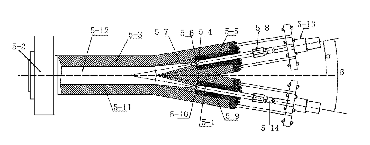
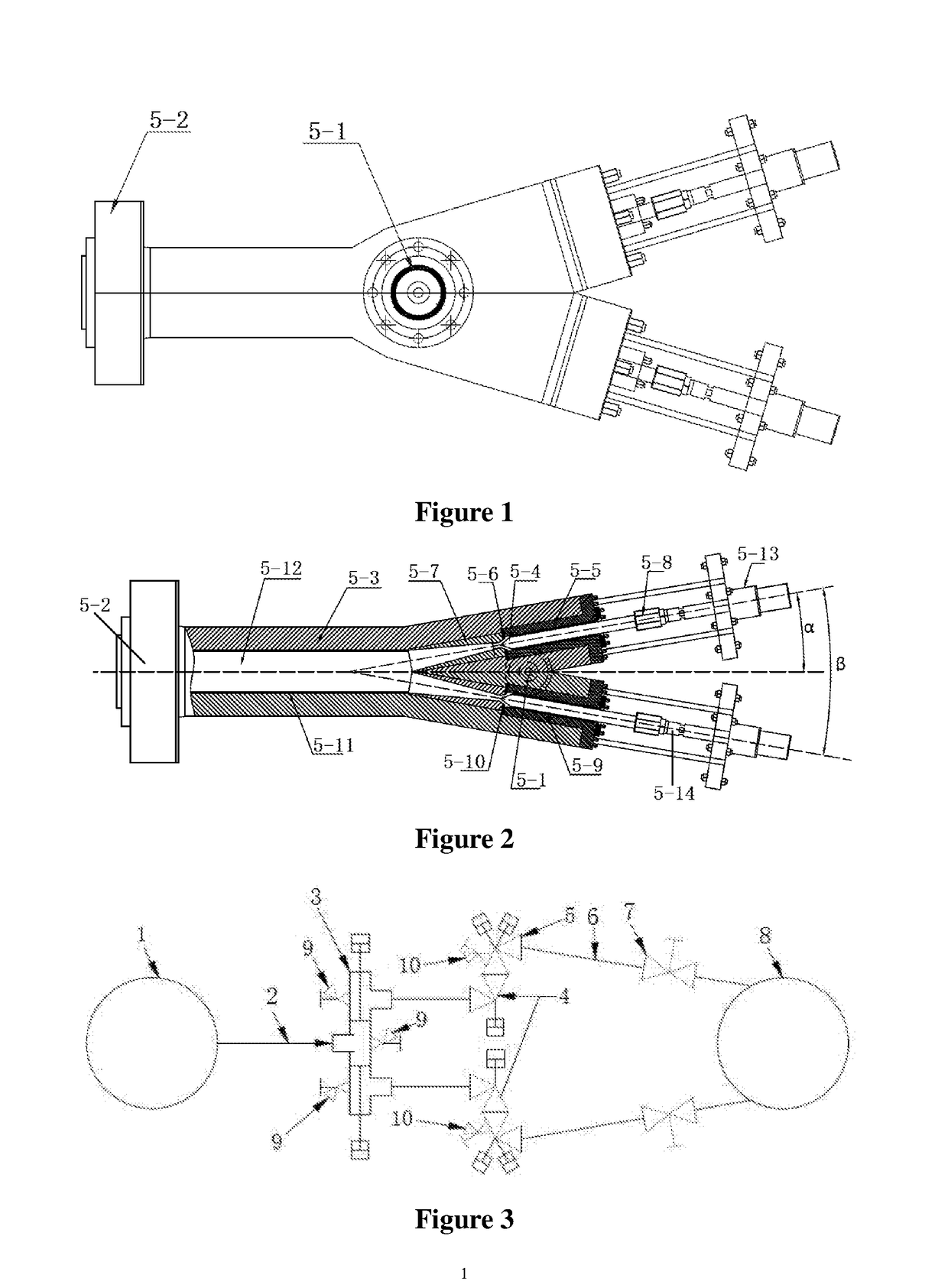
[0061]The present invention provides a pressure reducing valve, illustrated in FIGS. 1 and 2, which comprises a main valve body 5-3, having a valve chamber formed therein, and also having a valve outlet 5-2 and a valve inlet 5-1 which are disposed thereon and respectively communicated with the valve chamber; comprises at least two pressure reducing devices, disposed between the valve inlet 5-1 and the valve outlet 5-2, and adapted for depressurizing fluid at the valve inlet 5-1 before discharging to the valve outlet 5-2. In the present embodiment, there are two (2) pressure reducing devices; in other embodiments, there can be three or more pressure reducing devices. In the present embodiment, there is one valve inlet 5-1 and one valve outlet 5-2.

[0062]In the pressure reducing valve provided above, the configuration only occupies a small space, and may have low cost and less high pressure leakage point. The pressure reducing devices share one main valve body, which are independent of...

embodiment 2

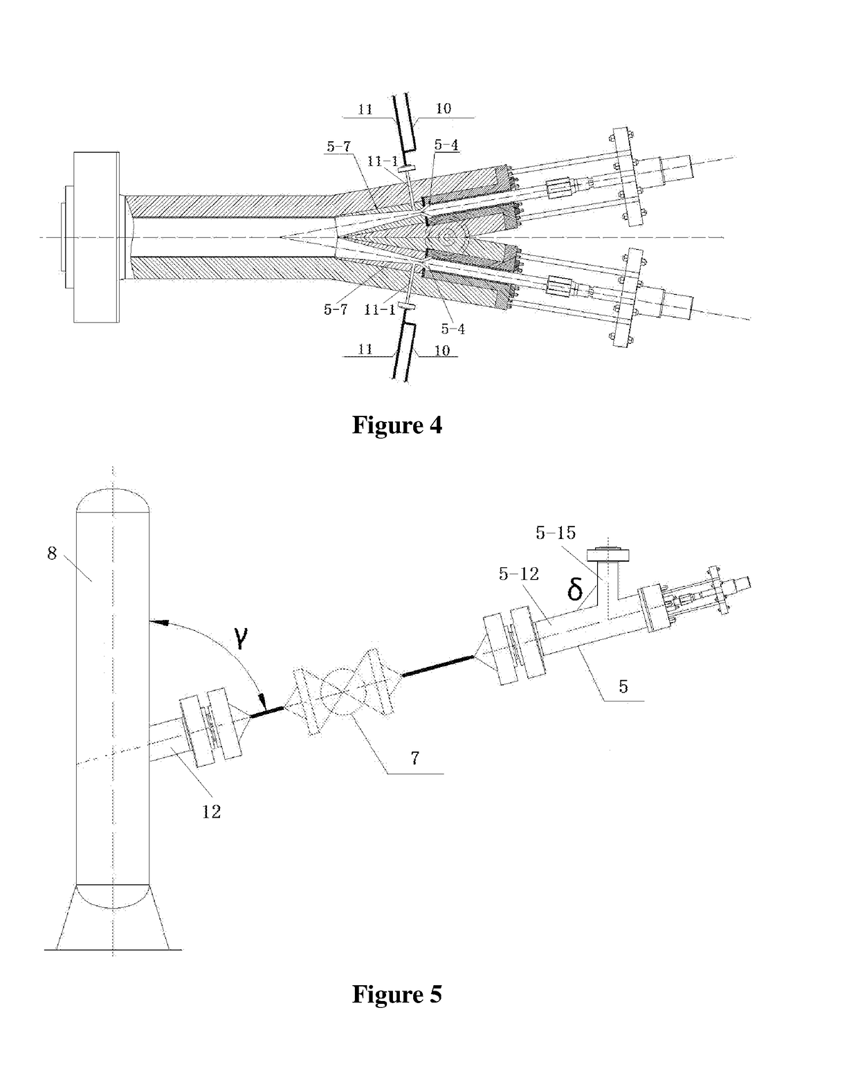
[0085]The embodiment of the present invention provides a pressure reducing system, as shown in FIGS. 3, 4 and 5, comprising a high pressure separator 1, a low pressure separator 8, and at least one pressure reducing member disposed between the high pressure separator 1 and the low pressure separator 8, and the pressure reducing component comprises at least one pressure reducing member 5 including a valve body, a valve chamber formed in the valve body, a valve seat 5-7 provided in the valve chamber, and a valve core 5-4 extending into the valve chamber and cooperating with the valve seat 5-7 to adjust the size of the fluid passage; the pressure reducing member further comprises at least one regulating member 11 including an adjustment medium outlet section 11-1 through which the valve body and the valve seat 5-7 are communicate with the valve chamber.

[0086]In the above-mentioned pressure reducing system, at least one regulating member 11 is provided, and the regulating member include...


PUM


Abstract

A pressure reducing valve and a pressure reducing system are provided. The pressure reducing valve includes a main valve body in which a valve chamber is formed; the main valve body is provided with a valve outlet and a valve inlet communicating with the valve chamber; and at least two pressure reducing devices adapted between the valve inlet and the valve outlet to depressurize the fluid at the valve inlet and discharge to the valve outlet. The pressure reducing valve occupies a small space, low cost and low pressure leakage point. Each pressure reducing device shares a main valve body, independent of each other, do not interfere with each other, and can be flexible to switch or use at the same time. The pressure reducing system is provided with at least one regulating member, which comprising an adjustment medium outlet section which communicates with the valve chamber through the valve body and the valve seat. Through the regulating member to reduce erosion and wear caused by the cavitation effect, and adjust the fluid flow flexibly.

Description

TECHNICAL FIELD[0001]The present invention relates to the field of coal chemical and petrochemical technology, particularly relates to a pressure reducing valve and a pressure reducing system, and more particularly relates to a pressure reducing valve and a pressure reducing system that reduces pressure of a hot high-pressure separator for suspension bed hydrogenation to make it as a hot low-pressure separatorBACKGROUND OF THE INVENTION[0002]In the coal tar hydrogenation industry, the existing processes are like fixed bed hydrogenation, suspension bed hydrogenation and fluidized bed hydrogenation. No matter what kind of process, need to be carried after the reaction of hydrogen and part of the catalyst and other substances in the oil and gas from the high-pressure separator into the low-pressure separator, and after pressure is reduced, to achieve gas-liquid separation.[0003]In the above mentioned pressure reducing occasions, the differential pressure from the high pressure separato...

Claims


Application Information

Patent Timeline
Patent Type & Authority Applications(United States)
IPC IPC(8): G05D16/10F16K1/12F16K11/10
CPCG05D16/106F16K1/12F16K11/105G05D16/0404G05D16/10
Inventor LI, LINGUO, LIXINWANG, NALI, ZHENDUOLU, YANGWANG, PEIPEI
Owner BEIJING HUASHI UNITED ENERGY TECH & DEV
Features
  • R&D
  • Intellectual Property
  • Life Sciences
  • Materials
  • Tech Scout
  • Unparalleled Data Quality
  • Higher Quality Content
  • 60% Fewer Hallucinations
Learn More