Antenna, method of manufacturing antenna, and touch sensor

a manufacturing method and touch sensor technology, applied in the direction of antenna equipment with additional functions, instruments, radiating element structural forms, etc., can solve the problems of difficult narrowing down the band width and high surface electrical resistance, and achieve satisfactory sensitivity, low volume, and low visibility

Active Publication Date: 2018-02-15
FUJIFILM CORP
View PDF9 Cites 15 Cited by
  • Summary
  • Abstract
  • Description
  • Claims
  • Application Information

AI Technical Summary

Benefits of technology

[0010]The purpose of the present invention is to solve the problems in the related art described above and to provide an antenna having low visibility, satisfactory sensitivity, and low occupation of a volume in a device provided with the antenna, a method of manufacturing an antenna, and a touch sensor.
[0018]According to the antenna and the method of manufacturing an antenna of the present invention, it is possible to obtain an antenna having low visibility, satisfactory sensitivity, and low occupation of a volume in a device provided with the antenna.
[0019]According to the touch sensor of the present invention, it is possible to cause a touch sensor to have an antenna having low visibility, satisfactory sensitivity, and low occupation of a volume in a device provided with the antenna.

Problems solved by technology

In JP2013-257755A, there is a problem in that surface electrical resistance is 15 to 900 Ω / sq. due to the existence of the dispersing agent used in dispersion of the gold fine particles, and surface electrical resistance is high for the use in an antenna.
In WO2006 / 106982A, there is a problem in that, in a case where the band width of the extra-fine band is narrowed down, and electroplating is performed, ignition occurs, and thus it is difficult to narrow down the band width.

Method used


Image

  • Antenna, method of manufacturing antenna, and touch sensor
  • Antenna, method of manufacturing antenna, and touch sensor
  • Antenna, method of manufacturing antenna, and touch sensor

Examples


example 1

[0260]Polyacrylic acid (viscosity: 8,000 to 12,000 cp, manufactured by Wako Pure Chemical Industries, Ltd.), a tetrafunctional acrylamide A (a monomer in which all “R's” in Formula (4) were represented by methyl groups, synthesized according to JP5486536B) as a polyfunctional monomer, and monofunctional acrylamide (N-t-butylacrylamide) as a monofunctional monomer were dissolved in isopropanol in a solid mass ratio of 1:0.33:0.33, and then irgacure (registered trademark) 127 (polymerization initiator, manufactured by BASF SE) was dissolved so as to be 5 wt % with respect to the total mass of the polyfunctional monomer and the monofunctional monomer described above, so as to prepare a plated layer forming composition (hereinafter, also referred to as a “composition”) in a solid content concentration of 3 mass %.

[0261]A hard coat polyethylene terephthalate film (H522 (product name) manufactured by Lintec Corporation) which was a substrate was coated with the obtained composition by usi...

example 2

[0267]Compared with Example 1, Example 2 was the same as Example 1 except that the line width of the metal fine wires was 3 μm, and thus the detailed description is omitted.

example 3

[0268]Compared with Example 1, Example 3 was the same as Example 1 except that the line width of the metal fine wires was 5 μm and the number of metal fine wires was 40, and thus the detailed description is omitted.


PUM


Abstract

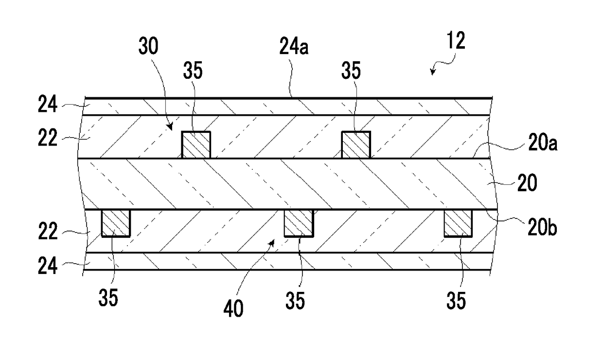
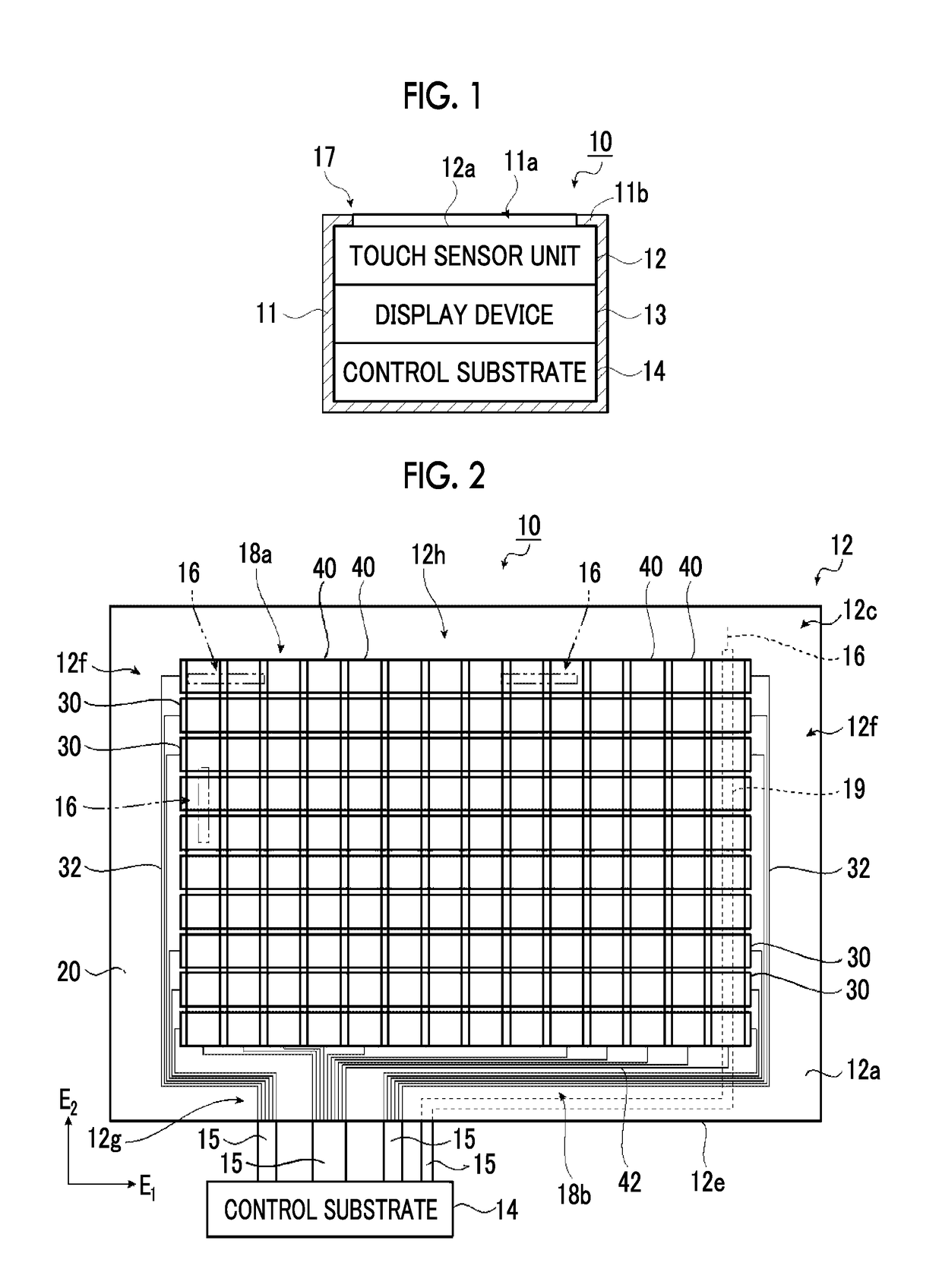
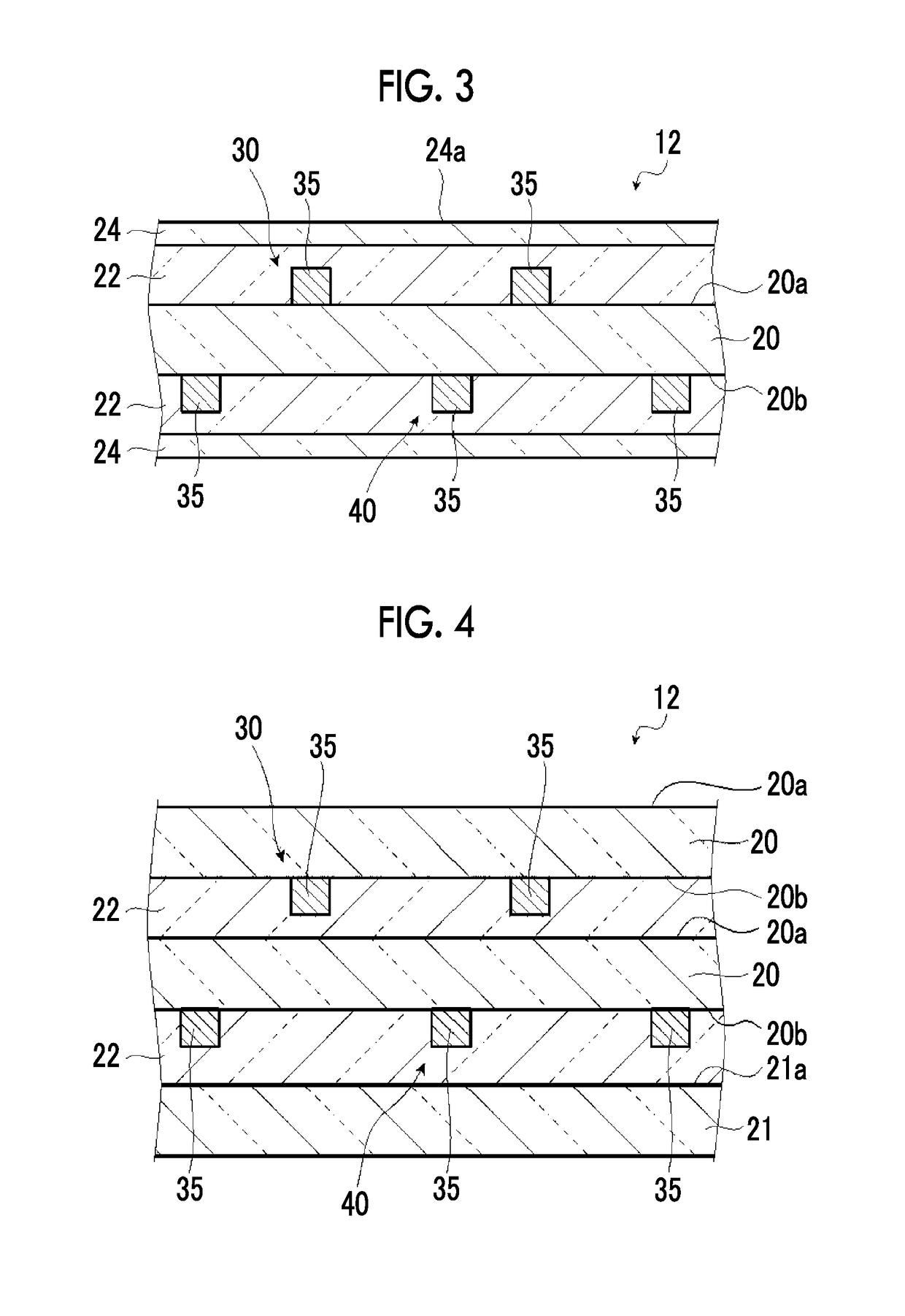
An antenna has a visible light transparent substrate, and a pattern including metal fine wires provided on the visible light transparent substrate and having a plurality of opening portions. In the pattern, a line width of the metal fine wire is 0.5 to 5.0 μm, an opening ratio is 70% or greater, and surface electrical resistance is 9 Ω / sq. or less. A method of manufacturing an antenna has a step of forming a pattern in which a line width of metal fine wires is 0.5 to 5.0 μm, and an opening ratio is 70% or greater by an electroless copper plating treatment. A touch sensor has a touch sensor unit which is provided in a visible light transparent substrate and which includes at least a detection electrode in which a plurality of opening portions are formed of conductive fine wires, and at least one antenna provided on the substrate.

Description

CROSS-REFERENCE TO RELATED APPLICATIONS[0001]This application is a Continuation of PCT International Application No. PCT / JP2016 / 063860 filed on May 10, 2016, which claims priority under 35 U.S.C. §119(a) to Japanese Patent Application No. 2015-102219 filed on May 19, 2015. The above application is hereby expressly incorporated by reference, in its entirety, into the present application.BACKGROUND OF THE INVENTION1. Field of the Invention[0002]The present invention relates to an antenna used in a mobile terminal device having a touch sensor, which is called a smart phone, a tablet, or a smart watch, a method of manufacturing an antenna, and a touch sensor, and particularly relates to an antenna having small occupation of a volume of a mobile terminal device, low visibility, and satisfactory sensitivity, a method of manufacturing an antenna, and a touch sensor.2. Description of the Related Art[0003]Currently, advance in function, miniaturization, thinning, and weight reduction of a mo...

Claims


Application Information

Patent Timeline
Patent Type & Authority Applications(United States)
IPC IPC(8): G06F3/044H01Q13/10H01Q1/24H01Q1/44H01Q1/22H01Q1/38
CPCG06F3/044H01Q1/22H01Q1/38H01Q1/243H01Q1/44H01Q13/106G06F2203/04103G06F3/0445G06F3/0446G06F2203/04112H01Q1/1271
Inventor YOSHIDA, MASAFUMITADA, NOBUYUKI
Owner FUJIFILM CORP
Why Eureka
Try Eureka