Contactless smart card comprising an antenna optimized to allow embossing of characters

a technology antennas, which is applied in the field of contactless smart cards comprising antennas optimized to allow embossing of characters, can solve problems such as damage or even cutting antenna tracks, degrading the cohesion of layers, and complicated problems

Active Publication Date: 2018-02-15
SMART PACKAGING SOLUTIONS SPS
View PDF2 Cites 3 Cited by
  • Summary
  • Abstract
  • Description
  • Claims
  • Application Information

AI Technical Summary

Benefits of technology

[0014]According to the principle of the invention, the wide tracks located under the embossing area are divided into two or more narrower tracks therefore less sensitive to delamination and electrically connected in parallel. Moreover, in order to prevent these narrower tracks from being cut when embossing the characters the narrow tracks are positioned on the insert in such a way that at least one of the tracks of each set of tracks in parallel remains outside the area of the characters, in such a manner that the embossing operation can never cut the electrical continuity of the antenna, even allowing for the tolerance for positioning the antenna (and therefore the tracks) in the card body.
[0021]The two divided tracks connected in parallel are preferably connected by interconnection bridges, which has the effect of limiting the effect of cutting of some tracks during the embossing of the characters. The width of the interconnection bridges is then substantially equal to T−j+2c, where T designates the tolerance for positioning the antenna in the card body, j designates the interval between two character columns, and c designates the minimum remaining track thickness to ensure the electrical continuity of the track.

Problems solved by technology

Now, the embossing process for creating characters in relief by stamping on the finished card body integrating the insert including the antenna can damage or even cut the antenna tracks in the area in which the antenna and the embossed characters must coexist.
But this problem is complicated by the fact that the tolerance for positioning the antenna in the card body is of the order of 1.5 mm.
However, this widening of the antenna tracks has created a new problem in that experience shows that wider antenna tracks degrade the cohesion of the layers constituting the card body.
Consequently, the wider the antenna tracks, the greater the risk of delamination.

Method used


Image

  • Contactless smart card comprising an antenna optimized to allow embossing of characters
  • Contactless smart card comprising an antenna optimized to allow embossing of characters
  • Contactless smart card comprising an antenna optimized to allow embossing of characters

Examples


Embodiment Construction

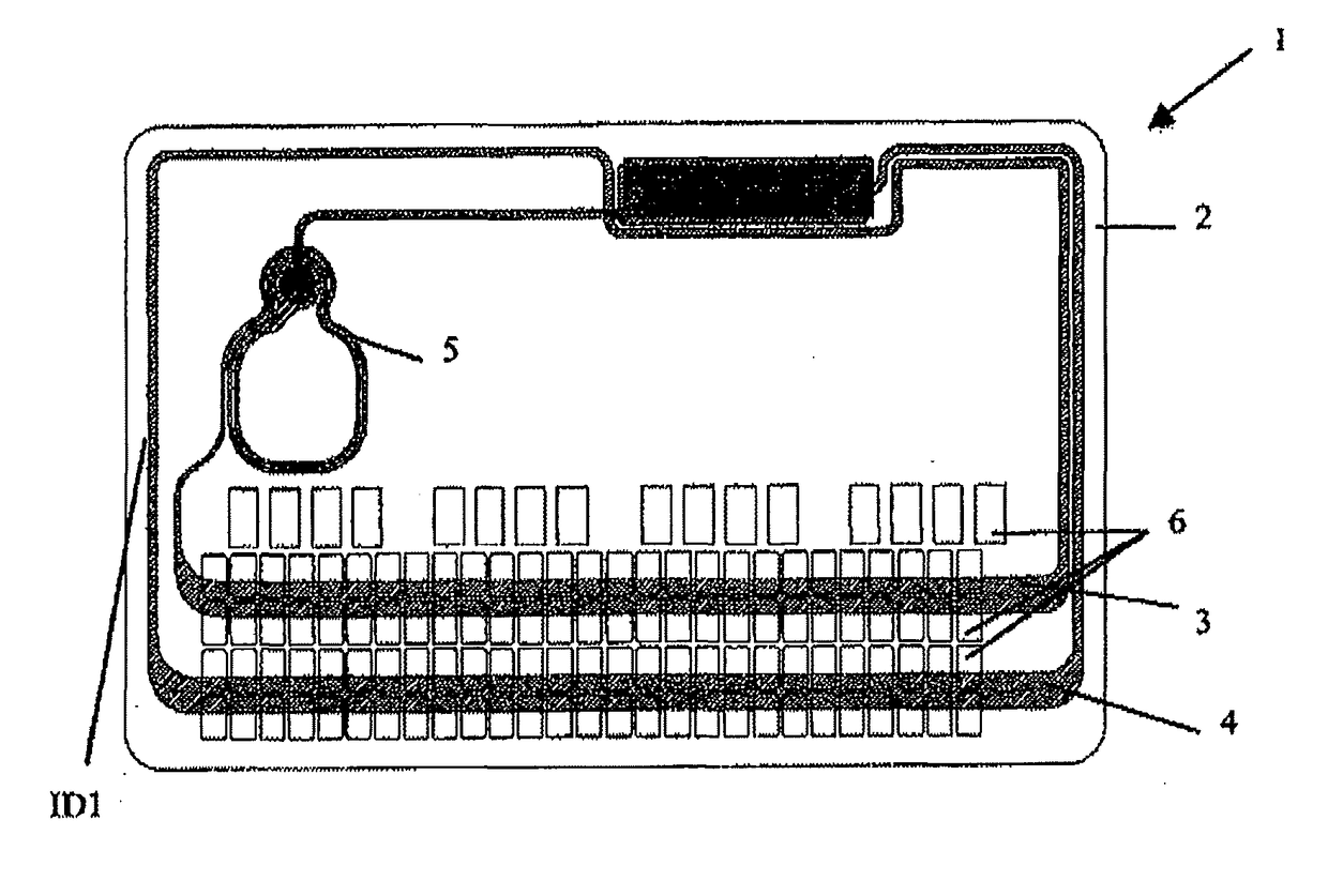
[0034]Turn to FIG. 1. The known smart card 1, shown in plan view, includes a card body 2 including an antenna ID1, termed the main antenna, consisting of two turns of large size, and a secondary antenna or concentrator 5 intended to concentrate the electromagnetic flux. The turns of the antenna ID1 (simply denoted ID1 in FIG. 1), namely the turns of large size that run along the card edges and therefore have a format close to the ID1 format, overlap the area of the card body intended to receive the lines 6 of alphanumeric characters. The locations of the characters to be embossed are represented by rectangles and the characters themselves are not shown and vary from one card to another.

[0035]Given the tolerance T of approximately 1.5 mm for positioning the antenna ID1 in the card body, the horizontal sections of the turns of the antenna ID1 can be at positions varying from one card to another. In particular, the tracks 3, 4 of the antenna ID1 can be superimposed on a line 6 of chara...


PUM


Abstract

The invention relates to an antenna for a contactless smart card, arranged on an insert intended to be integrated in said smart card having a certain relative vertical or horizontal positioning tolerance T between the insert and the body of the card, said smart card being provided with an embossing area comprising lines of characters embossed in relief, at least one antenna coil being situated opposite the embossing area, wherein said coil comprises at least one pair of paths situated in the embossing area and connected in parallel, said paths being configured in such a way that at least one of same remains at least partially situated outside of the embossed character area whatever the relative position of the insert and the antenna of same allowed by the tolerance T.

Description

[0001]The invention concerns contactless or hybrid identification cards operating with or without contact and including an area of embossed characters on the card body and an antenna integrated into the card body to communicate remotely with a card reader. Contactless bank cards conforming to the ISO 7816-1 format constitute the most widespread example of the identification cards to which the invention applies.PRIOR ART[0002]Most known contactless smart cards or dual cards operating with and without contact include a card body, an electronic module inserted in a cavity of the card body and including a microelectronic die, and an antenna disposed in the card body and electrically connected to output terminals of the microelectronic die.[0003]Alternatively, there are smart cards in which the antenna of the card body is coupled inductively with the electronic module that itself includes an antenna.[0004]The antenna of the card body generally consists of turns consisting of electrically...

Claims


Application Information

Patent Timeline
Patent Type & Authority Applications(United States)
IPC IPC(8): G06K19/077
CPCG06K19/07769G06K19/07773G06K19/042G06K19/07749
Inventor MEAR, BENJAMINKAMBOURIAN, HAIGTEBOUL, DEBORAH
Owner SMART PACKAGING SOLUTIONS SPS
Why Eureka
Try Eureka