
Fluororubber-metal laminate sheet

a technology of fluorubber and metal laminate sheet, which is applied in the direction of metal layered products, synthetic resin layered products, engine components, etc., can solve the problems of affecting the performance of the engine, the deterioration of the pot life of the coating solution, and the substantial loss of productivity, so as to achieve less environmental load, less voc discharge, and the effect of reducing the effect of voc discharg

Active Publication Date: 2013-07-02
NOK CORP
View PDF10 Cites 0 Cited by
  • Summary
  • Abstract
  • Description
  • Claims
  • Application Information

AI Technical Summary

Benefits of technology

The solution provides enhanced sealability, compression resistance, anti-freezing liquid resistance, and long-term durability while reducing environmental load and processing costs, with improved surface smoothness and non-stickiness, and maintaining performance across various tests.

Problems solved by technology

The inorganic filler showing low friction factor is hard to disperse, and the particle size of the filler is consequently larger, and particularly in cylinder head gaskets, etc. in the product rubber layer thickness as small as about 25 μm the seal surface is much roughened, giving an adverse effect on the sealability.
Furthermore, when the proportion of admixed amine-containing silane coupling agent exceeds 4 parts by weight on the basis of 100 parts by weight of fluororubber, the pot life of the coating solution, i.e. the fluororubber-mixed paint, is considerably deteriorated, where the productivity is substantially lost.
However, the chromating treatment involves an environmental load problem, and rubber-metal laminate sheets produced by application of a chromating substitute treatment for the metal sheet, followed by multi-layer coating also have a heavy environmental load from the total product side, in view of the complicated treating process, and further are costwise inadvantageous.

Method used


Image

  • Fluororubber-metal laminate sheet
  • Fluororubber-metal laminate sheet
  • Fluororubber-metal laminate sheet

Examples


example 1

[0044]

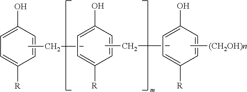
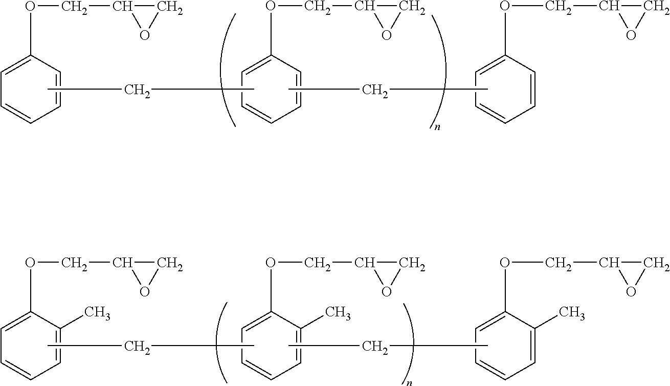
Parts by weightFluororubber (Viton A-200, a product of DuPont)100MT carbon black (N990)20White carbon (Nipsil ER, a product of Toso-Silica Co.)10Amorphous graphite (A-O, a product of Nichiden Carbon30Co,; max. particle size: 45 μm; average particle size:13 μm)Magnesium oxide (Magnesia #30, a product of Kyowa5Chemical Co.)Vulcanizing agent (Curative #30, a product of DuPont;4bisphenol AF: 50 wt. %, and fluororubber (Viton E-45):50 wt. %)Vulcanization accelerator (Curative #20, a product of2DuPont; organic phosphonium salt: 33 wt. %, andfluororubber (Viton F-45): 67 wt. %)Silane coupling agent (APZ-6633, a product of Toray •2.5Dow Corning)(in terms ofsolid matters)Epoxy-modified phenol resin (Epiclon N695, a product4of Dainippon Ink & Chemicals)

[0045]The foregoing components except the vulcanization accelerator were kneaded together through a pressure kneader, thereafter discharging rubber compounds, and then mixed with the vulcanization accelerator through open rolls to give a ...

example 2

[0073]In Example 1, the amount of amorphous graphite was changed to 10 parts by weight.

example 3

[0074]In Example 1, the amount of amorphous graphite was changed to 50 parts by weight.


PUM

PropertyMeasurementUnit
particle sizeaaaaaaaaaa
thicknessaaaaaaaaaa

Abstract

A fluororubber-metal laminate sheet, which comprises a metallic sheet and a vulcanized fluorocarbon layer, provided on the metallic sheet by applying thereto a fluororubber composition comprising (A) 100 parts by weight of a polyol-vulcanizable fluororubber, (B) 10-50 parts by weight of amorphous graphite, (C) 1-15 parts by weight of a phenol resin, (D) 1-4 parts by weight of a silane coupling agent, (E) 0.5-8 parts by weight of a polyol-based vulcanizing agent, and (F) 0.5-6 parts by weight of a vulcanizing accelerator, followed by vulcanization of the fluororubber composition to form laminate, where the metallic sheet is free from either a chromating treatment or a chromating substitute treatment, is distinguished in characteristics such as sealability, compression resistance, air-heated aging resistance, anti-freezing liquid resistance, oil resistance, sticking resistance, abrasion resistance, etc.

Description

RELATED APPLICATION[0001]This application is a 35 U.S.C. §371 national phase filing of International Patent Application No. PCT / JP2009 / 064905, filed Aug. 27, 2009, through which and to which priority is claimed under 35 U.S.C. §119 to Japanese Patent Application No. 2008-230514, filed Sep. 9, 2008.TECHNICAL FIELD[0002]The present invention relates to a fluororubber-metal laminate sheet, and more particularly a fluororubber-metal laminate sheet for use as effective automobile gaskets, etc.BACKGROUND ART[0003]A metal gasket comprising a bead sheet and a coating material provided thereon by coating the bead sheet with a rubber-mixed paint comprising 100 parts by weight of fluororubber, 50-200 parts by weight of an inorganic lubricant such as graphite, carbon, and molybdenum dioxide, and 4-16 parts by weight of a silane coupling agent, followed by vulcanization, has been so far proposed as a gasket metal sheet coated with a coating material capable of maintaining high slippability and n...

Claims


Application Information

Patent Timeline
Patent Type & Authority Patents(United States)
IPC IPC(8): B32B15/06B32B25/14
CPCC08L27/18F16J15/122B05D2202/00B05D2530/00C08K3/04C08K5/54Y10T428/25C08L61/14C08L61/06C08L2666/14Y10T428/31529Y10T428/3154Y10T428/31678B32B15/04B32B15/06F16J15/06F16J15/12
Inventor YOKOTA, ATSUSHIHIGASHIRA, TOSHIHIROKITAJIMA, YASUAKI
Owner NOK CORP
Learn More