
Semiconductor switching string

a switching string and semiconductor technology, applied in the field can solve the problems of many semiconductor switching elements having inherent limitations in their performance, difficult operation, etc., and achieve the effect of stable operation of semiconductor switching strings, reducing voltage overshoots, and optimising the peak time and rise time of such voltage overshoots

Inactive Publication Date: 2018-02-15
GENERAL ELECTRIC TECH GMBH
View PDF3 Cites 0 Cited by
  • Summary
  • Abstract
  • Description
  • Claims
  • Application Information

AI Technical Summary

Benefits of technology

The patent describes a control system that can quickly and reliably turn on and off auxiliary semiconductor switches in a short period of time, without the need for feedback on the status of each main switch. This control system uses a higher level control unit that implements a first model based control methodology. The resulting switching signal operates each associated auxiliary switch in a reliable manner.

Problems solved by technology

This creates difficulties in the operation of, e.g. a power converter in which the semiconductor switching elements are incorporated.
In addition, many semiconductor switching elements have inherent limitations in their performance which require the inclusion of large, heavy and difficult-to-design remedial components within, e.g. a power converter, to compensate for these shortcomings.

Method used


Image

  • Semiconductor switching string
  • Semiconductor switching string
  • Semiconductor switching string

Examples


Embodiment Construction

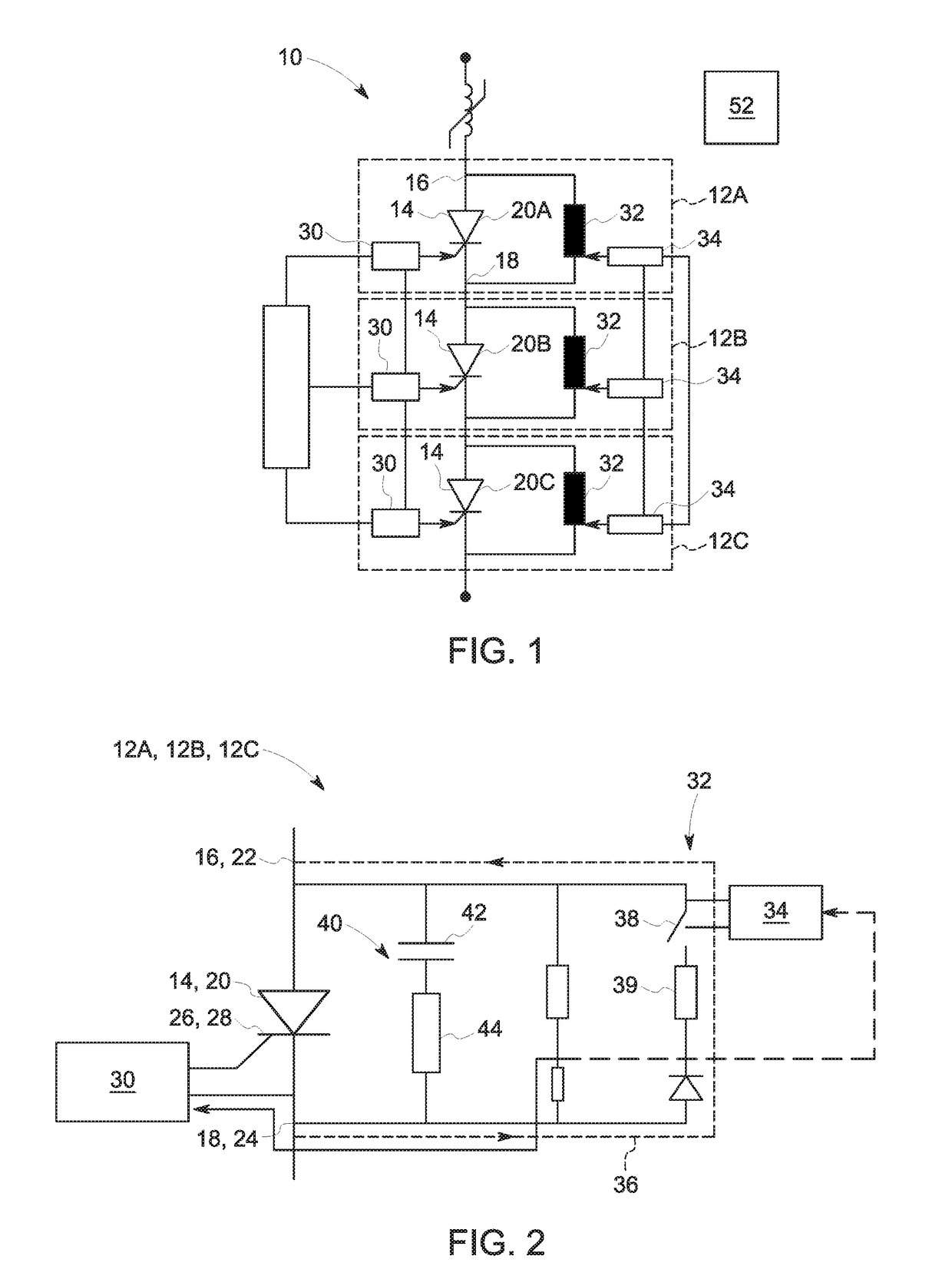
[0047]A semiconductor switching string according to embodiments of the invention is designated generally by reference numeral 10, as shown in FIG. 1.

[0048]The semiconductor switching string 10 includes a plurality of series-connected semiconductor switching assemblies 12. Three such semiconductor switching assemblies 12A, 12B, 12C are shown in FIG. 1, by way of illustration, whereas in practice the semiconductor switching string 10 is likely to include many tens or hundreds of semiconductor switching assemblies 12.

[0049]As shown in FIG. 2, each semiconductor switching assembly 12 has a main semiconductor switching element 14 that includes first and second connection terminals 16, 18. In the embodiment shown the main semiconductor switching element 14 is a main thyristor 20, although in other embodiments of the invention a different semiconductor switching element may be used such as a diode, Light-Triggered Thyristor (LTT), Gate Turn-Off thyristor (GTO), Gate Commutated Thyristor (G...


PUM


Abstract

A semiconductor switching string including a series-connected switching assemblies. Each assembly has a main switching element including first and second connection terminals which current flows between when the main switching element is on. The main element has an auxiliary element between the connection terminals. The string includes a local control unit connected with each auxiliary element which are programmed to switch an auxiliary element to create an alternative current path between the connection terminals that diverts current through to reduce the voltage across the corresponding main switching element. The local unit is programmed to control switching an auxiliary element to a fully-on mode in which the auxiliary element is at maximum rated base current, a pulsed mode which turns the auxiliary element on and off and / or an active mode operating the auxiliary element with a continuously variable base current. The string includes a higher level control unit programmed to implement the modes.

Description

FIELD OF THE INVENTION[0001]Embodiments of the invention relate to a semiconductor switching string for use in a power converter, such as a high voltage direct current (HVDC) power converter.BACKGROUND OF THE INVENTION[0002]In power transmission networks alternating current (AC) power is typically converted to direct current (DC) power for transmission via overhead lines and / or under-sea cables. This conversion removes the need to compensate for the AC capacitive load effects imposed by the transmission line or cable and reduces the cost per kilometre of the lines and / or cables, and thus becomes cost-effective when power needs to be transmitted over a long distance.[0003]Power converters are used to convert AC power to DC power. Semiconductor switching elements, such as thyristors, are a key component of power converters, and act as controlled rectifiers to convert AC power to DC power and vice versa.[0004]While such semiconductor switching elements have very high breakdown voltages...

Claims


Application Information

Patent Timeline
Patent Type & Authority Applications(United States)
IPC IPC(8): H03K17/16H02M1/088H03K17/06
CPCH03K17/16H03K17/06H02M1/088H03K5/02H03K5/04H02M1/34H02M7/7575H03K17/08144H03K17/105H02M1/344Y02E60/60
Inventor EFIKA, IKENNA BRUCEDAVIDSON, COLIN CHARNOCK
Owner GENERAL ELECTRIC TECH GMBH
Learn More