
Distance-measuring imaging device, distance measuring method of distance-measuring imaging device, and solid-state imaging device

a technology of distance measurement and imaging device, which is applied in the direction of distance measurement, radiation controlled devices, instruments, etc., can solve the problems of reducing distance measurement accuracy and conventional techniques having difficulty in achieving both a wide distance measurement range and high distance measurement accuracy. , to achieve the effect of widening the distance measurement range, high distance measurement accuracy, and not increasing the pulse width of the light sour

Active Publication Date: 2018-02-22
NUVOTON TECH CORP JAPAN
View PDF10 Cites 19 Cited by
  • Summary
  • Abstract
  • Description
  • Claims
  • Application Information

AI Technical Summary

Benefits of technology

The present invention provides a device and method for measuring distance using imaging technology. The device can accurately measure the distance to both the near and far sides without the need to increase the pulse width of the light source. This makes it easier to measure the distance of objects at a wider range of distances.

Problems solved by technology

In other words, increasing the pulse width (To) of the light source to widen distance measurement range (limit) D causes a decrease in distance measurement accuracy.
The conventional technique therefore has difficulty in achieving both a wide distance measurement range and high distance measurement accuracy.

Method used


Image

  • Distance-measuring imaging device, distance measuring method of distance-measuring imaging device, and solid-state imaging device
  • Distance-measuring imaging device, distance measuring method of distance-measuring imaging device, and solid-state imaging device
  • Distance-measuring imaging device, distance measuring method of distance-measuring imaging device, and solid-state imaging device

Examples


embodiment 1

Variation of Embodiment 1

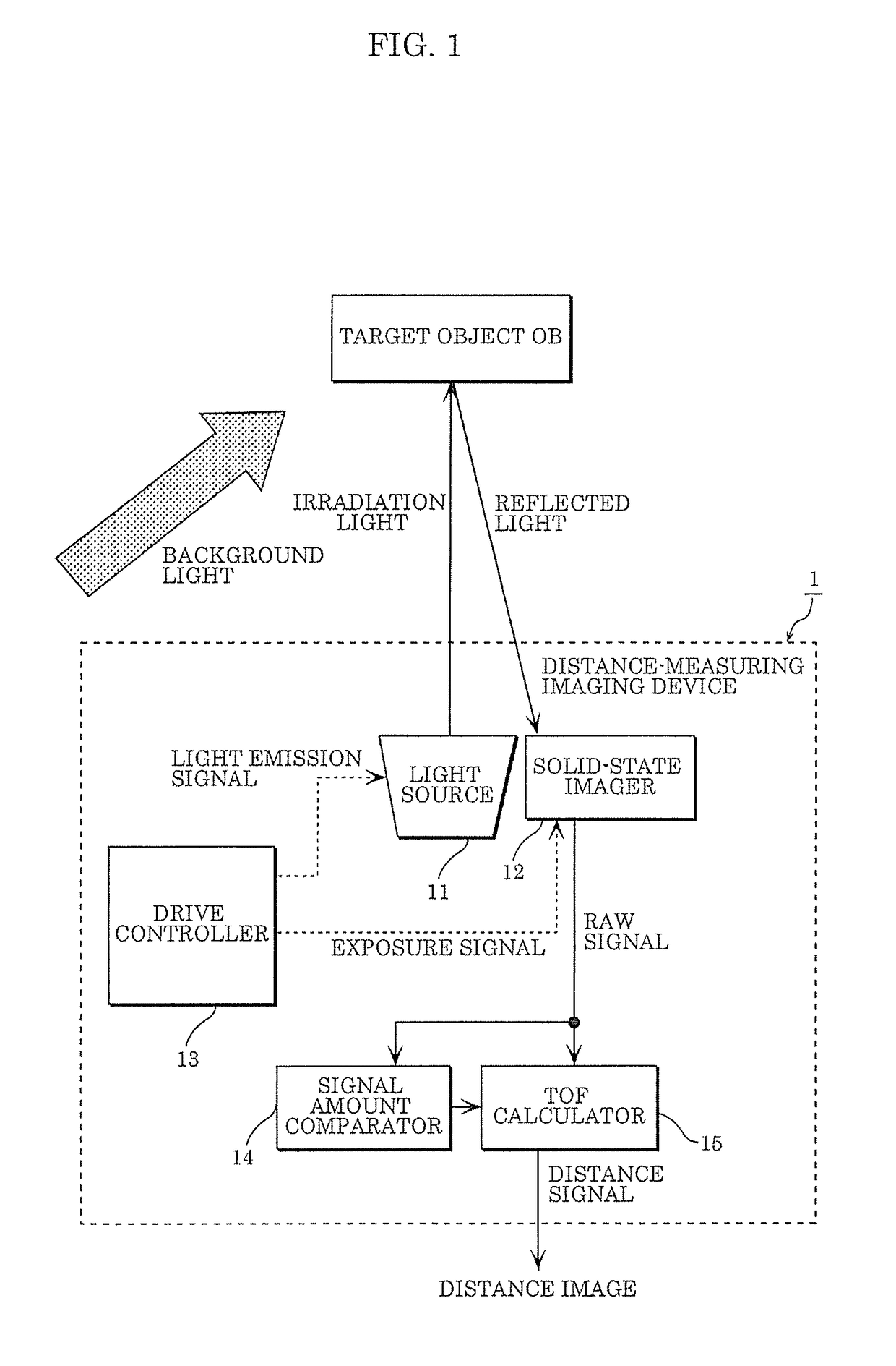
[0064]FIG. 7 is a functional block diagram illustrating an example of the schematic structure of a signal amount comparator in a distance-measuring imaging device according to a variation of Embodiment 1. As illustrated in FIG. 7, signal amount comparator 24 includes noise remover 26, signal separator 27, background light remover 28, and abnormal value determinator 29.

[0065]Noise remover 26 removes noise from raw data received from solid-state imager 12.

[0066]Signal separator 27 separates the plurality of signals involving reflected light and the signal involving only background light, from the magnitude relationship in signal amount between the signals accumulated in the plurality of different signal accumulators in the noise-removed raw data received from noise remover 26. Signal separator 27 notifies the determination result of the magnitude relationship in signal amount to TOF calculator 25 (distance calculator 25).

[0067]Background light remover 28 subtr...

embodiment 2

Variation 2 of Embodiment 2

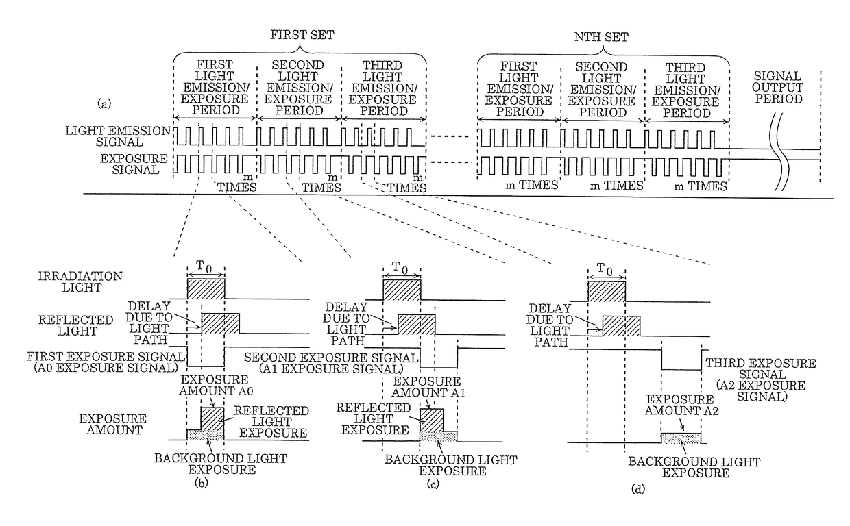
[0110]FIG. 14 is a timing chart of the light emission signal and the exposure signal in distance-measuring imaging device 1 according to Variation 2 of Embodiment 2. In detail, the drawings illustrate an example of the timing relationship between the light emission signal and the exposure signal generated by drive controller 13. In particular, the drawings each illustrate the timings of the light emission signal and exposure signal on the same paper surface, to ease the understanding of the relationship between a plurality of exposure periods that differ in the timing of the exposure signal for receiving reflected light. This embodiment describes an example where the number of different signal accumulators for accumulating signals detected in the same pixel in solid-state imager 12 is 4.

[0111]Drive controller 13 outputs the first, second, third, and fourth exposure signals that differ in the timing at which solid-state imager 12 receives reflected light fr...


PUM


Abstract

A distance-measuring imaging device includes a light source that applies light according to timing of a light emission signal; a solid-state imager that performs, for an object, exposure according to timing of an exposure signal, and generates raw data corresponding to an exposure amount of the exposure; a signal amount comparator that determines a magnitude relationship in signal amount in the raw data; and a distance calculator that generates and outputs a distance signal based on a determination result. The solid-state imager accumulates, in each of different signal accumulation regions for accumulating signals detected in a same pixel, a signal by exposure in an exposure period that differs in exposure signal timing. The signal amount comparator determines the magnitude relationship between the signals accumulated in the signal accumulation regions. The distance calculator calculates the distance to the object using an arithmetic expression selected depending on the determination result.

Description

CROSS REFERENCE TO RELATED APPLICATIONS[0001]This application is a U.S. continuation application of PCT International Patent Application Number PCT / JP2016 / 002297 filed on May 10, 2016, claiming the benefit of priority of Japanese Patent Application Number 2015-108867 filed on May 28, 2015, the entire contents of which are hereby incorporated by reference.BACKGROUND1. Technical Field[0002]The present disclosure relates to a distance-measuring imaging device, a distance measuring method of the distance-measuring imaging device, and a solid-state imaging device.2. Description of the Related Art[0003]Of a plurality of methods for detecting an object, a time of flight (TOF) method of measuring a distance using a time of flight during which light travels to and from a measurement object is known.[0004]Japanese Unexamined Patent Application Publication No. 2004-294420 (Patent Literature (PTL) 1) discloses the following conventional technique: Charges are transferred to two different signal...

Claims


Application Information

Patent Timeline
IPC IPC(8): H01L27/146G01S7/486H01L31/101H04N5/335G01C3/06G01S17/10G01S7/4863G01S17/89G01S17/894
CPCH01L27/14609H01L27/14641G01S7/4863H01L31/101H04N5/335G01C3/06G01S17/10G01S7/4876G01S17/894H04N25/00G01S17/89H04N25/40
Inventor OTANI, MITSUHIKOMATSUO, JUNICHITAKANO, HARUKA
Owner NUVOTON TECH CORP JAPAN
Learn More