Polyurethane filter foam
Active Publication Date: 2018-03-01
HYUNDAI MOTOR CO LTD
View PDF1 Cites 1 Cited by
- Summary
- Abstract
- Description
- Claims
- Application Information
AI Technical Summary
Benefits of technology
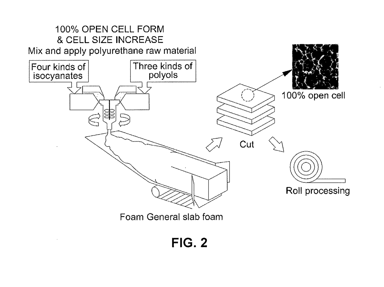
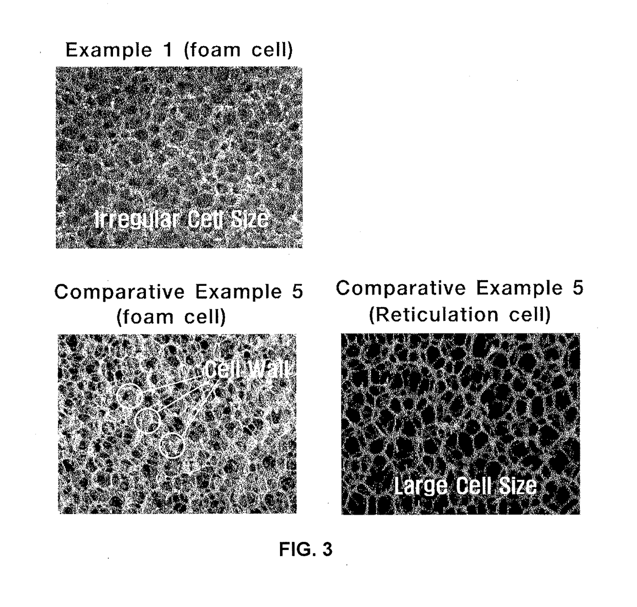
The present invention relates to a polyurethane filter foam that has improved production stability and reduced production costs. By controlling cell size and regularity through changes in raw material composition, the foam has reduced generation of bad smell and a reduced risk of gas explosion during hot heat treatment. Additionally, the foam has improved generation of good smell and reduced overall error rate as compared to the foam in the related art.
Problems solved by technology
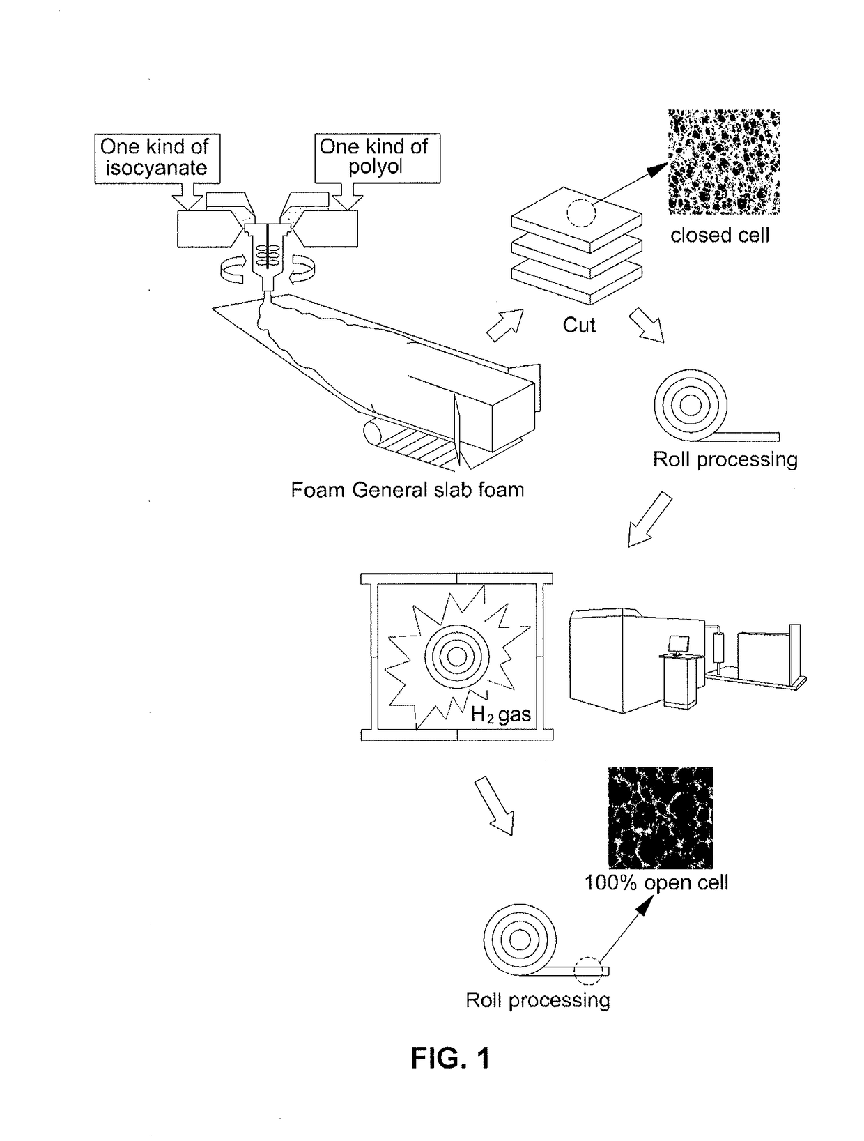
The manufactured foam is soft slab foam having a dense and uniform cell structure and permeability is insufficient to be applied as the filter foam.
However, when the size of the cell is large and a large amount of gas is simultaneously discharged at the time when the foam is opened, a collapse possibility is increased.
Herein, since making the large cell in the closed cell structure is not a normal manufacturing process, various defects such as collapse of the foam during foaming and a mixed defect may occur.
Method used
View moreImage
Smart ImageViewing Examples
Examples
preparation example 1
Preparation of Isocyanate Mixture
[0068]An isocyanate mixture was prepared by mixing (B-1) 60 wt % of MDI monomers,
[0069](B-2) 10 wt % of carbodiimide modified MDI having weight average molecular weight of 300 g / mol,
[0070](B-3) 20 wt % of polymeric MDI having weight average molecular weight of 350 g / mol, and
[0071](B-4) 10 wt % of MDI prepolymer having weight average molecular weight of 500 g / mol.
Login to View More PUM
| Property | Measurement | Unit |
|---|---|---|
| Percent by mass | aaaaa | aaaaa |
| Percent by mass | aaaaa | aaaaa |
| Molar mass | aaaaa | aaaaa |
Abstract
A polyurethane filter foam is provided herein. The polyurethane filter foam may have improved permeability by having both a small cell and a large cell in a range for maximizing the opening property of the foam. In some instance, this is achieved by specifically configuring and foaming a composition of polyether polyol and methylene diphenyl diisocyanate (MDI) to manufacture the polyurethane foam. The polyurethane foam of the present invention can be manufactured without performing a reticulation process.
Description
CROSS-REFERENCE TO RELATED APPLICATION[0001]This application claims under 35 U.S.C. §119(a) the benefit of Korean Patent Application No. 10-2016-0111986, filed on Aug. 31, 2016, the entire contents of which are incorporated herein by reference for all purposes.BACKGROUNDTechnical Field[0002]The present invention relates to polyurethane filter foam, and more particularly, a polyurethane filter foam with improved permeability by having both a plurality of small cells and a plurality of large cells in a range that maximizes an open cell structure in the foam. The polyurethane filter foam of the present invention can be manufactured by specifically configuring and foaming a composition of polyether polyol and methylene diphenyl diisocyanate (MDI).Background Art[0003]Polyurethane is a polymer synthesized by polymerization of polyol and isocyanate. The polyurethane foam can be foamed by the generation of carbon dioxide gas as water which is used as a blowing agent reacts with isocyanate a...
Claims
Login to View More Application Information
Patent Timeline
 IPC IPC(8): C08G18/48C08G18/76C08G18/79B01D39/16
CPCC08G18/48C08G18/7671C08G2101/0083B01D39/1676C08G18/797B01D46/0001B01D46/30C08G18/3206C08G18/4804C08G18/4841C08G18/6674C08G18/794C08G2340/00C08G2110/0083C08G18/6677C08G18/7657C08G18/7664C08G18/18C08G2110/0058B01D39/00C08G18/10C08G18/4812C08G18/4816C08G18/4833C08J9/00C08L75/08C08G2101/00C08J2375/08
Inventor LIM, BYUNG GUKPARK, SANG DOJEONG, DONG WOOKANG, SEOK NAMLEE, HOON BOKHAN, KUG HUNKIM, SANG HOCHOI, KWON YONGJUNG, SOON JOONLEE, SUNG HOONKIM, MU YOUNGKIM, KYUNG SAMCHO, YOO KONLEE, SUNG IL
Owner HYUNDAI MOTOR CO LTD
- R&D Engineer
- R&D Manager
- IP Professional
- Industry Leading Data Capabilities
- Powerful AI technology
- Patent DNA Extraction
Learn More Browse by: Latest US Patents, China's latest patents, Technical Efficacy Thesaurus, Application Domain, Technology Topic, Popular Technical Reports.
© 2024 PatSnap. All rights reserved.Legal|Privacy policy|Modern Slavery Act Transparency Statement|Sitemap|About US| Contact US: help@patsnap.com


