Eureka AIR delivers breakthrough ideas for toughest innovation challenges, trusted by R&D personnel around the world.

Vortices induced helical fluid delivery system

Active Publication Date: 2018-03-01
ESTEBAN RESENDEZ
View PDF11 Cites 0 Cited by
  • Summary
  • Abstract
  • Description
  • Claims
  • Application Information

AI Technical Summary

Benefits of technology

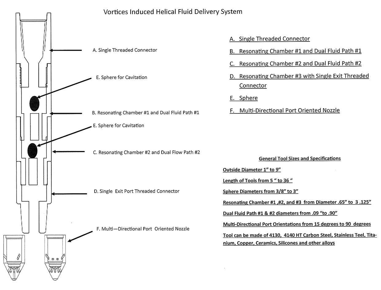
The invention is designed to create a fluid pattern that has three different flow patterns: cavitation, helical, and acoustic. This is done without any mechanical moving parts, and can be done at varying pressures, temperatures, and volumes. The invention uses small hydraulically driven bearings in each chamber to reduce the total flow area, which helps to accelerate the fluid or gas as it exits the technology. This invention has no limitations in terms of fluid type or pressure range, making it highly versatile.

Problems solved by technology

Current technologies can only create one or two type of fluid patterns, which limits the functionality when cleaning out Wells.
However, the moving parts increase the need for repair and maintenance.

Method used


Image

  • Vortices induced helical fluid delivery system
  • Vortices induced helical fluid delivery system
  • Vortices induced helical fluid delivery system

Examples


Embodiment Construction

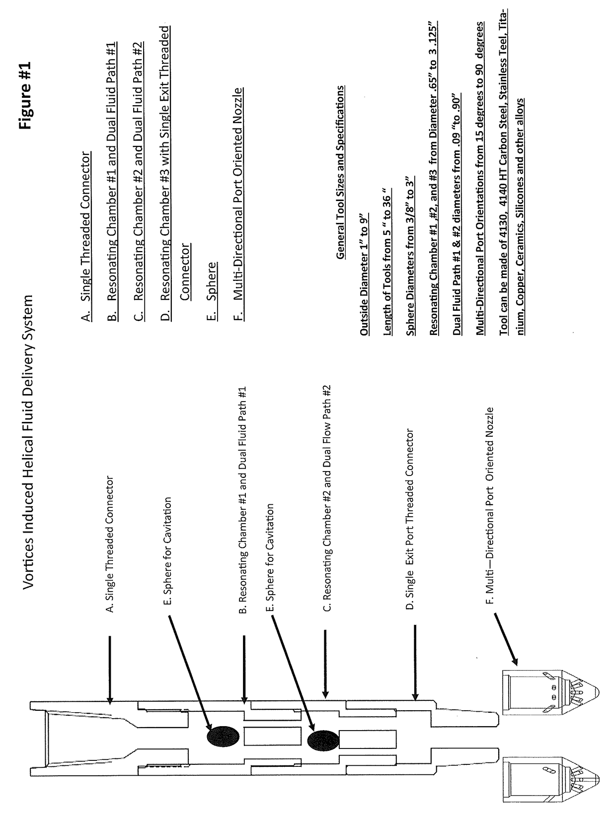
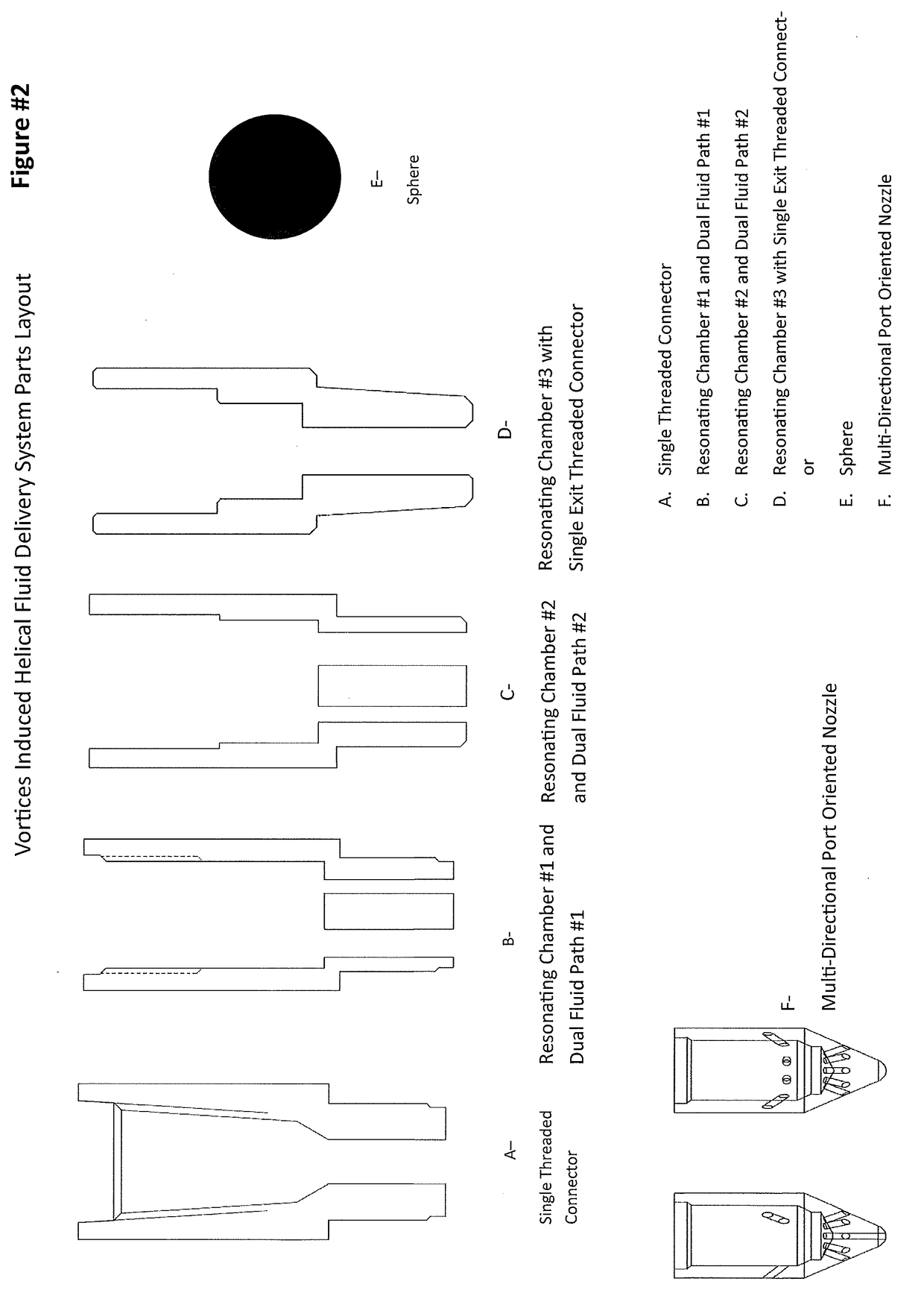
[0006]Referring now to the invention in more detail, FIG. 1 of the present invention, which can be made of 4140 carbon steel, stainless steel, ceramics, titanium, or other alloys, shows how fluid enters through a fluid entry & resonating expansion chamber #1, where a vortices effect is created; and into dual fluid paths #1, which induce the helical pattern; then enters a resonating expansion chamber #2, where the two flow paths are comingled and the vortices effect is enhanced; then flows through dual fluid paths #2, which maintains the induced helical pattern; then comingled into an expansion chamber #3; where the vortices effect is maintained until it flows out of the multi-port oriented nozzle head with port orientations of 15, 30, 45 and 90 degrees. The fluid may also exit out through a single exit point that connects to a drill string. FIG. 1 also shows the bearings / spheres, which can be of varying size, that can be placed in each chamber that are hydraulically driven that redu...


PUM


Abstract

A vortices induced helical fluid delivery system that creates a fluid pattern with cavitation, helical and acoustic (pulsating) oscillating methods with no mechanical moving parts within the technology without being limited to pressures, temperatures, volumes or fluid type that more efficiently clean out scale and debris build-up from a productive or formerly productive oil, gas or wastewater wells, including perforations and near region that surrounds the well. There are varying sized bearings / spheres that can be placed in each chamber that are hydraulically driven that reduce the total flow area (instead of slow down the fluid). The technology can be externally altered to encompass drill string operations to help improve drilling operations by reducing friction and improving annular fluid flow by the inherent vibration that is created by the technology.

Description

FIELD OF THE INVENTION[0001]The present invention is in the technical field of oil, gas, water and wastewater well (“Well(s)”) for the purpose of assisting with properly cleaning out the Well, perforations and near region that surrounds the Well from scale and debris (remediation). More particularly, the present invention is in the field of well intervention and drilling technologies and apparatus to help improve production of the Wells, including perforations and near region that surrounds the Wells.BACKGROUND OF THE INVENTION[0002]Current flow patterns, which consist of static flow, cavitation, acoustic (pulsating) and oscillation, helical, and spinning nozzles, are limited to pressures, temperatures, fluid type and volumes. Current technologies can only create one or two type of fluid patterns, which limits the functionality when cleaning out Wells. Some may have mechanical moving parts to create such patterns during operation. However, the moving parts increase the need for repa...

Claims


Application Information

Patent Timeline
IPC IPC(8): E21B37/00
CPCE21B37/00E21B10/61E21B41/0078
Inventor RESENDEZ, ESTEBAN
Owner ESTEBAN RESENDEZ
Why Eureka
Eureka Blog
Learn More