Methods for the controlled reduction of turbine nozzle flow areas and turbine nozzle components having reduced flow areas

Active Publication Date: 2013-08-08
HONEYWELL INT INC
View PDF10 Cites 14 Cited by
  • Summary
  • Abstract
  • Description
  • Claims
  • Application Information

AI Technical Summary

Benefits of technology

[0006]Embodiments of a turbine nozzle component are further provided. In one embodiment, the turbine nozzle component includes an inner endwall, an outer endwall radially spaced from the inner endwall, and a plurality of nozzle vanes extending between the inner and outer endwalls. A plurality of turbine nozzle flow paths extend

Problems solved by technology

It is, however, difficult to manufacture a turbine nozzle having an ideal turbine flow area in an efficient, highly-controlled, and cost-effective manner.
For example, in instances wherein a number of individual turbine nozzle segments are separately cast and assembled to produce a turbine nozzle ring assembly, it is often difficult to produce nozzle segments having tightly controlled inner dimensions due to uncertainties inherent in the casting process, such as dimensional changes resulting from metal shrinkage during cooling.
While it is possible to fine tune part dimensions via the production of multiple molds in a trial-and-error process, such a practice is time consum

Method used


Image

  • Methods for the controlled reduction of turbine nozzle flow areas and turbine nozzle components having reduced flow areas
  • Methods for the controlled reduction of turbine nozzle flow areas and turbine nozzle components having reduced flow areas
  • Methods for the controlled reduction of turbine nozzle flow areas and turbine nozzle components having reduced flow areas

Examples


Example

[0014]The following Detailed Description is merely exemplary in nature and is not intended to limit the invention or the application and uses of the invention. Furthermore, there is no intention to be bound by any theory presented in the preceding Background or the following Detailed Description. Terms such as “comprise,”“include,”“have,” and variations thereof are utilized herein to denote non-exclusive inclusions. Such terms may thus be utilized in describing processes, articles, apparatuses, and the like that include one or more named steps or elements, but may further include additional unnamed steps or elements.

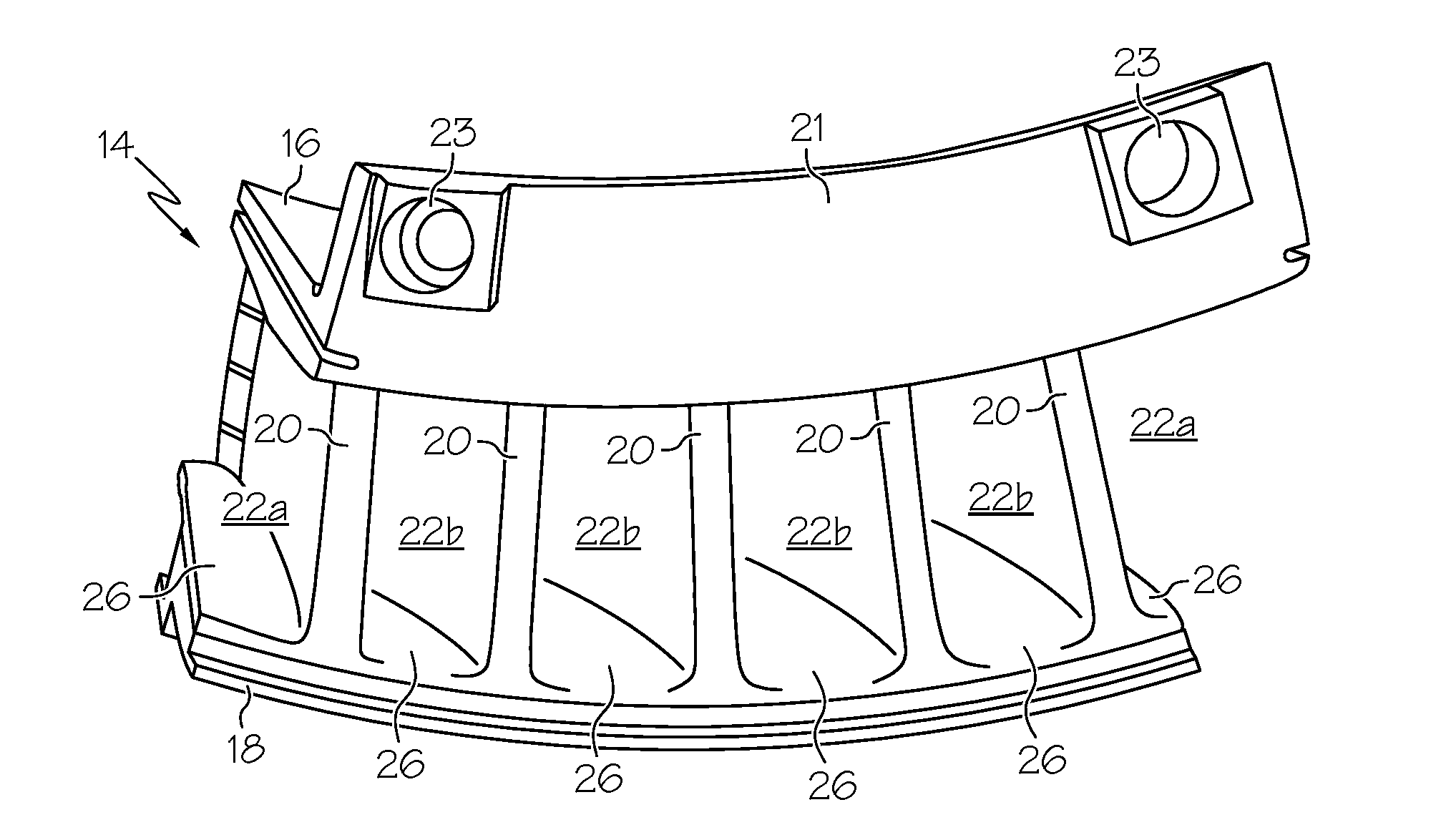
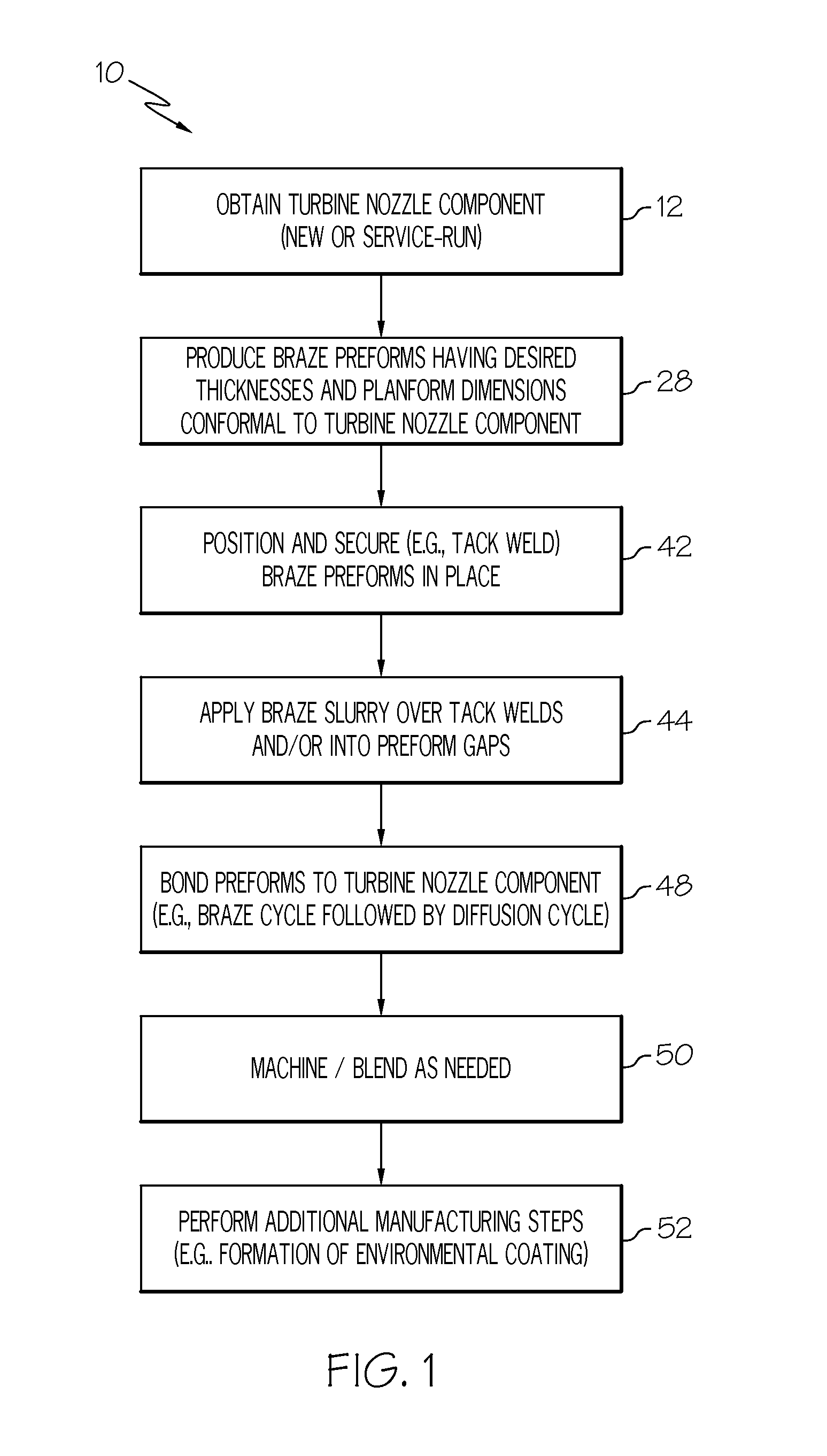
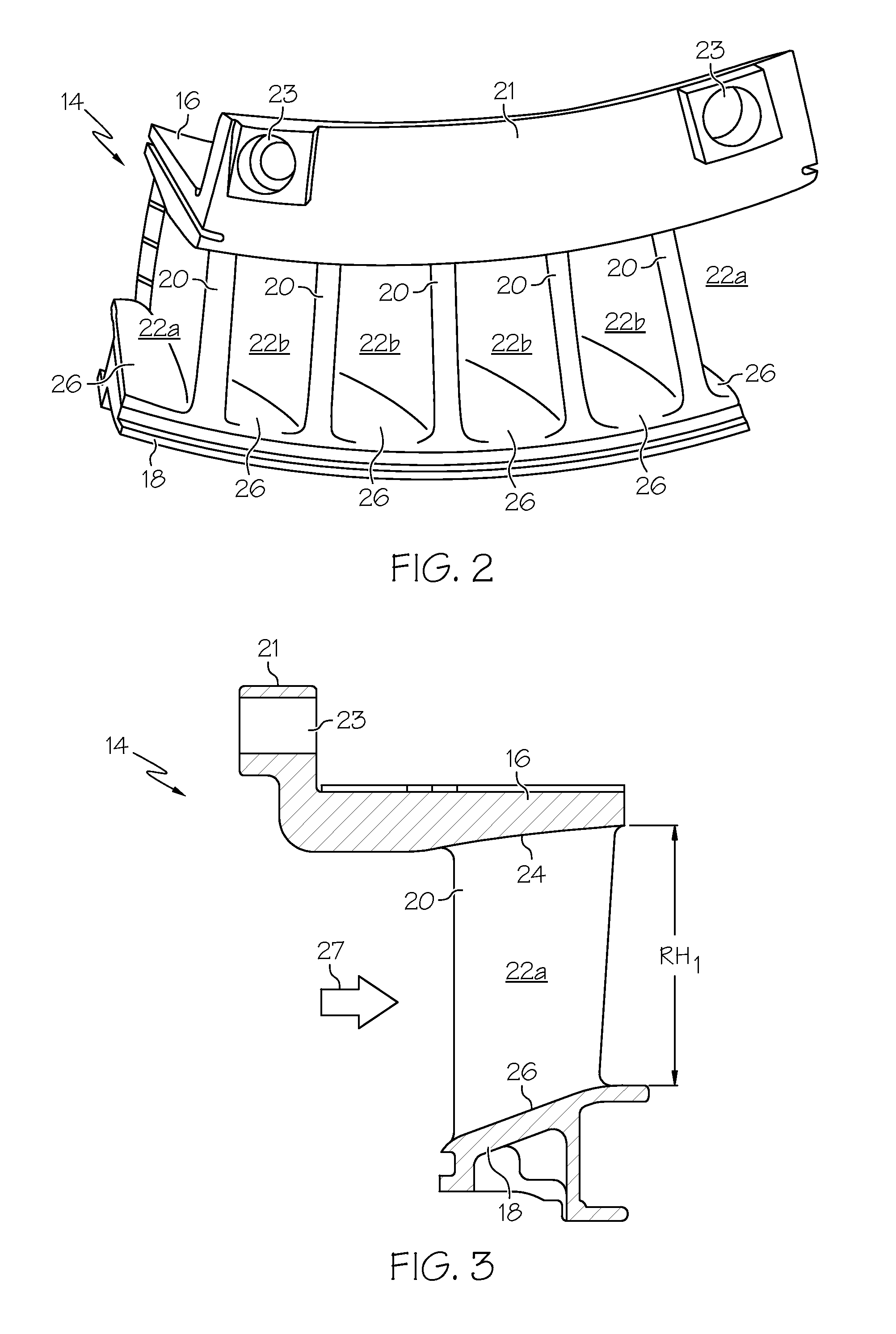
[0015]FIG. 1 is a flowchart illustrating an exemplary method 10 for reducing the effective flow area of a turbine nozzle component. The term “turbine nozzle component” is utilized herein to denote a turbine nozzle segment or other structure that can be mechanically attached to one or more additional components to produce a completed turbine nozzle assembly, such as a tur...


PUM

PropertyMeasurementUnit
Thicknessaaaaaaaaaa
Shrinkageaaaaaaaaaa
Electrical resistanceaaaaaaaaaa

Abstract

Embodiments of a method for controllably reducing of the flow area of a turbine nozzle component are provided, as are embodiments of turbine nozzle components having reduced flow areas. In one embodiment, the method includes the steps of obtaining a turbine nozzle component having a plurality of turbine nozzle flow paths therethrough, positioning braze preforms in the plurality of turbine nozzle flow paths and against a surface of the turbine nozzle component, and bonding the braze preforms to the turbine nozzle component to achieve a controlled reduction in the flow area of the turbine nozzle flow paths.

Description

TECHNICAL FIELD[0001]The following disclosure relates generally to gas turbine engines and, more particularly, to embodiments of a method for reducing the flow areas of turbine nozzle components, as well as to embodiments of turbine nozzle components having reduced flow areas.BACKGROUND[0002]During operation, a gas turbine engine compresses intake air, mixes the compressed air with fuel, and ignites the fuel-air mixture to produce combustive gasses, which are then expanded through a number of air turbines to drive rotation of the turbine rotors and produce power. Turbine nozzles are commonly positioned upstream of the turbine rotors to meter combustive gas flow, while also accelerating and turning the gas flow toward the rotor blades. A turbine nozzle typically assumes the form of a generally annular structure having a number of flow passages extending axially and tangentially therethrough. By common design, the turbine nozzle includes an inner endwall or shroud, which is generally ...

Claims


Application Information

Patent Timeline
IPC IPC(8): F01D9/02B23K31/02B23K1/00
CPCF05D2270/3061F01D25/28F01D9/04F01D11/008F05D2230/22F05D2240/80F01D9/041F01D9/047F05D2220/30F05D2230/21F05D2230/237F05D2240/128
Inventor MACELROY, BILL
Owner HONEYWELL INT INC
Why Eureka
Try Eureka