Friction drive with speed wheel and automatic traction control

a technology of automatic traction control and friction drive, which is applied in the direction of cycle, transportation and packaging, etc., can solve the problems of sudden and unpredictable changes in the power delivered to the wheel, sudden and reduced friction coefficient, and prone to slippage between the tire and the contact surface, so as to prevent slippage, accurately measure the speed of the tire, and reliably determine whether slippage is occurring

Inactive Publication Date: 2018-03-15
SHAREROLLER LLC
View PDF2 Cites 11 Cited by
  • Summary
  • Abstract
  • Description
  • Claims
  • Application Information

AI Technical Summary

Benefits of technology

[0014]The present disclosure relates to improved friction drive systems, control methods for friction drive systems, and automatic traction control for friction drive systems. Embodiments of a friction drive system include a speed wheel for accurately measuring the speed of a tire of a wheeled vehicle. By comparing the speed of the speed wheel to the speed of the drive motor (or contact surface), a control unit may reliably determine whether slippage is occurring. The control unit may send commands to adjust an amount of normal force between a contact surface on the drive motor and the tire in order to prevent slippage and maximize overall system efficiency, including by extending vehicle range and battery life. Moreover, the speed of the drive motor may be controlled in a way that minimizes any abrupt changes in vehicle speed when engaging the drive motor with the tire. Embodiments of a friction drive system disclosed herein can automatically adjust to changing conditions—for example, road, weather, or tire—in a safe and efficient manner.
[0019]Embodiments of a friction drive system may allow a user to calibrate or adjust the amount of normal force delivered based on their preferences or based on a selected mode of operation. Embodiments of the present disclosure may automatically disengage and reengage the contact surface of a friction drive with the tire (or wheel) of a wheeled vehicle in a safe and efficient manner.
[0020]Embodiments of the present disclosure may include an initialization procedure for determining a starting position of the contact surface relative to the tire, which advantageously may allow for rapid engagement with the tire when power is needed. Embodiments of the present disclosure may include a procedure for automatically engaging and disengaging the contact surface with the tire, such that engagement occurs when the motor is delivering power.
[0021]As would be understood by a person of skill in the art, embodiments of the present disclosure have applications beyond wheeled vehicles and may be used to improve the function, control, and performance of friction drive systems generally.

Problems solved by technology

When the coefficient of friction is suddenly reduced—for example, when the tire becomes wet after going through a puddle—slippage can occur between the tire and the contact surface.
Such slippage can be dangerous, because it can result in sudden and unpredictable changes to the power delivered to the wheel.
For example, after slipping, the tire may suddenly reengage (or “catch”) with the contact surface, causing a sudden increase in the power delivered to the wheel and in the resulting speed of the vehicle.
As another example, slippage could suddenly remove power from the wheel at a critical time, such as when trying to power away from an approaching vehicle or obstacle.
Known friction drive systems have difficulty responding to rapid changes in the amount of friction caused by weather (e.g., rain or snow), road conditions (e.g., dust or dirt), and other factors (e.g., loss of air in the tire).
However, such high-friction surfaces dramatically increase tire wear.
Moreover, the sandpaper (or other high-friction surface) needs to be regularly replaced as it wears down, which is a tedious and time consuming process that requires regular monitoring by the consumer.
However, continuously maintaining a large normal force requires more power due to tire churning, which drains the battery, and also increases tire wear.
Still other systems provide a limited ability to adjust the normal force by manually reconfiguring the system, for example, by pulling a lever or turning a screw; however, such systems are difficult to control and typically require the user to stop the vehicle and dismount in order to change the settings.
None of these known friction drive systems provide a simple mechanism for adjusting the normal force.
None of these known friction drive systems adjust the normal force dynamically in response to changing road conditions, weather, and the like.
None of these known friction drive systems provide automatic traction control between the friction drive and the tire (or wheel).
None of these known systems optimize the normal force to provide sufficient friction force to avoid slippage while minimizing tire wear and maximizing battery efficiency.
Another problem with known friction drive systems is that they do not automatically disengage from the tire (or wheel) when the motor is no longer in use.
Engaging with the tire (or wheel) when the motor is not actively providing power causes drag on the system, reduces efficiency, and slows the vehicle.
However, such systems are inefficient because the user frequently forgets to disengage the contact surface or is unable to disengage (and reengage) the contact surface with optimal timing.
Such known systems can also be dangerous; if the user reengages the contact surface when it is spinning at a high-differential speed compared to the tire, the power delivered to the tire (and the resulting speed of the vehicle) may change suddenly and unpredictably.
A problem with these known systems is that they can disengage at undesirable moments, for example, due to momentary lapses in power or physical jolts from bumpy roads.
Another problem with these systems is that they cannot stay engaged with the tire when the direction of force of the drive motor is reversed, for example, to provide regenerative braking.

Method used


Image

  • Friction drive with speed wheel and automatic traction control
  • Friction drive with speed wheel and automatic traction control
  • Friction drive with speed wheel and automatic traction control

Examples


Embodiment Construction

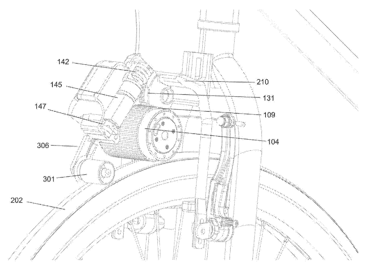
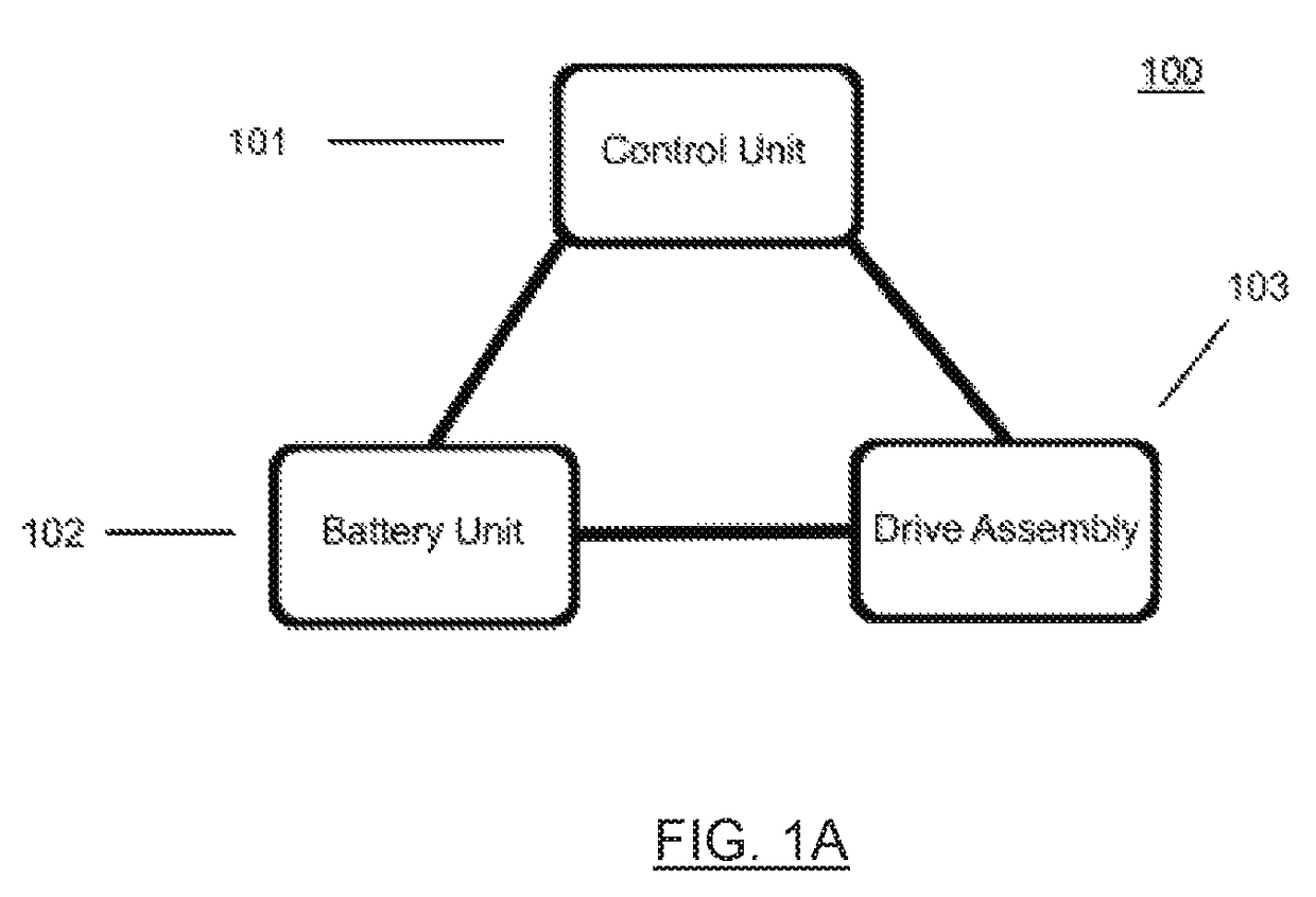
[0044]As shown in FIG. 1A, embodiments of friction drive system 100 include control unit 101, battery unit 102, and drive assembly 103. Battery unit 102 may provide electrical power to control unit 101 and drive assembly 103. Control unit 101 may provide control information (and commands) to battery unit 102 and drive assembly 103. Drive assembly 103 may provide power to a tire (or wheel) of a wheeled vehicle, or it may provide power to a hub or crank assembly of a wheeled vehicle, or it may provide power to another portion of the wheeled vehicle, depending on the particular embodiment. In some embodiments, friction drive system 100 may be provided as one or more separate units which may be mounted to a wheeled vehicle. In other embodiments, friction drive system 100 may be integrated with a wheeled vehicle, for example, as an electric bicycle, scooter, or wheelchair.

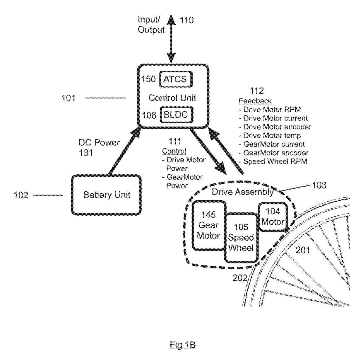
[0045]As shown in the embodiment of FIG. 1B, drive assembly 103 may include drive motor 104 and speed wheel 105. Driv...


PUM


Abstract

Embodiments of a friction drive system include a battery, a drive motor, a control unit, and a speed wheel. When the friction drive system is mounted on a wheeled vehicle, the speed wheel provides an accurate measurement of the vehicle speed by maintaining contact with a tire of the vehicle. An automatic traction control system, which may be part of the control unit, compares the speed of the speed wheel with the speed of the drive motor to determine whether slippage is occurring. If slippage is detected, then embodiments of an automatic traction control system automatically increase an amount of normal force between a contact surface on the drive motor and the tire, by advancing a position of the drive motor relative to a fixed mounting point. If no slippage is detected, then embodiments of an automatic traction control system automatically reduce the amount of normal force, by retracting a position of the drive r elative to a fixed mounting point. In embodiments of a friction drive system, the relative position of the drive motor may be controlled by powering a worm gear motor attached to a worm gear in response to commands from the control unit.

Description

CROSS-REFERENCE TO RELATED APPLICATIONS[0001]This application is a continuation-in-part of U.S. patent application Ser. No. 15 / 237,731, filed on Aug. 8, 2016, which claims the benefit of Provisional Patent Application No. 62 / 243,661, filed on Oct. 19, 2015. These applications are hereby incorporated by reference in their entirety.FIELD OF INVENTION[0002]The invention(s) disclosed herein relate to the field of friction drive systems, including friction drive systems that are capable of powering wheeled vehicles such as bicycles, scooters, wheelchairs, skateboards, strollers, wagons, tricycles, and other human powered vehicles. The inventions disclosed herein also may also be used with other devices, such as motorcycles, remote control vehicles, robots, wind turbines, manufacturing systems, conveyor belts, railcars, trains, printers, toys and consumer devices, among others.BACKGROUND[0003]Friction drive systems for powering wheeled vehicles, such as bicycles, have existed for many yea...

Claims


Application Information

Patent Timeline
Patent Type & Authority Applications(United States)
IPC IPC(8): B62M6/75
CPCB62M6/75B62M6/45B62M6/90F16H13/10B62M7/08B62M7/10F16B2/065B62M6/35
Inventor GUIDA, JEFFREY E.
Owner SHAREROLLER LLC
Why Eureka
Try Eureka