Fiber reinforced thermoplastic hoses and methods for forming the same

a fiber reinforced, thermoplastic hose technology, applied in the direction of synthetic resin layered products, mechanical instruments, other domestic articles, etc., can solve the problems of relatively hostile ambient conditions for thermoplastic hoses, high temperature for thermoplastic hoses,

Active Publication Date: 2018-03-15
EATON INTELLIGENT POWER LIMITED
View PDF7 Cites 4 Cited by
  • Summary
  • Abstract
  • Description
  • Claims
  • Application Information

AI Technical Summary

Benefits of technology

[0017]According to any of the hoses provided herein, the support thread of the inner fiber layer can have a nominal breaking strength, measured according to ASTM D7269, between about 50 lbs and about 125 lbs.
[0018]According to any of the hoses provided herein, a percent difference of nominal breaking strength, measured according to ASTM D7269, between the support thread of the inner fiber layer, the support thread of the intermediate fiber layer, and the support thread of the outer fiber layer is less than about 25%.
[0019]According to any of the hoses provided herein, the support thread of the inner fiber layer can be applied at an inner layer angle. The support thread of the intermediate fiber layer can be applied at an intermediate layer angle. The support thread of the outer fiber layer can be applied at an oute...

Problems solved by technology

Additionally, thermoplastic hoses can be subjected to relatively hostile ambient conditions.
Specifically, aircraft operation generally provides a relatively demanding ambient temperature range during normal operation due to use in a variety of climates and high altitude.
For example, thermoplastic hoses can be subjected to high temperatures, when exposed to engine environments, and low temperatures, when exposed to high altitude.
The combined impact of the pressurized conveyed material and the ambient op...

Method used


Image

  • Fiber reinforced thermoplastic hoses and methods for forming the same
  • Fiber reinforced thermoplastic hoses and methods for forming the same
  • Fiber reinforced thermoplastic hoses and methods for forming the same

Examples


embodiment 2

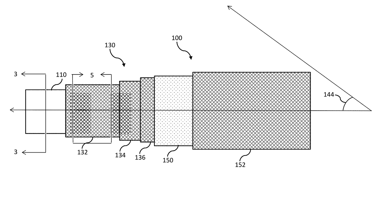
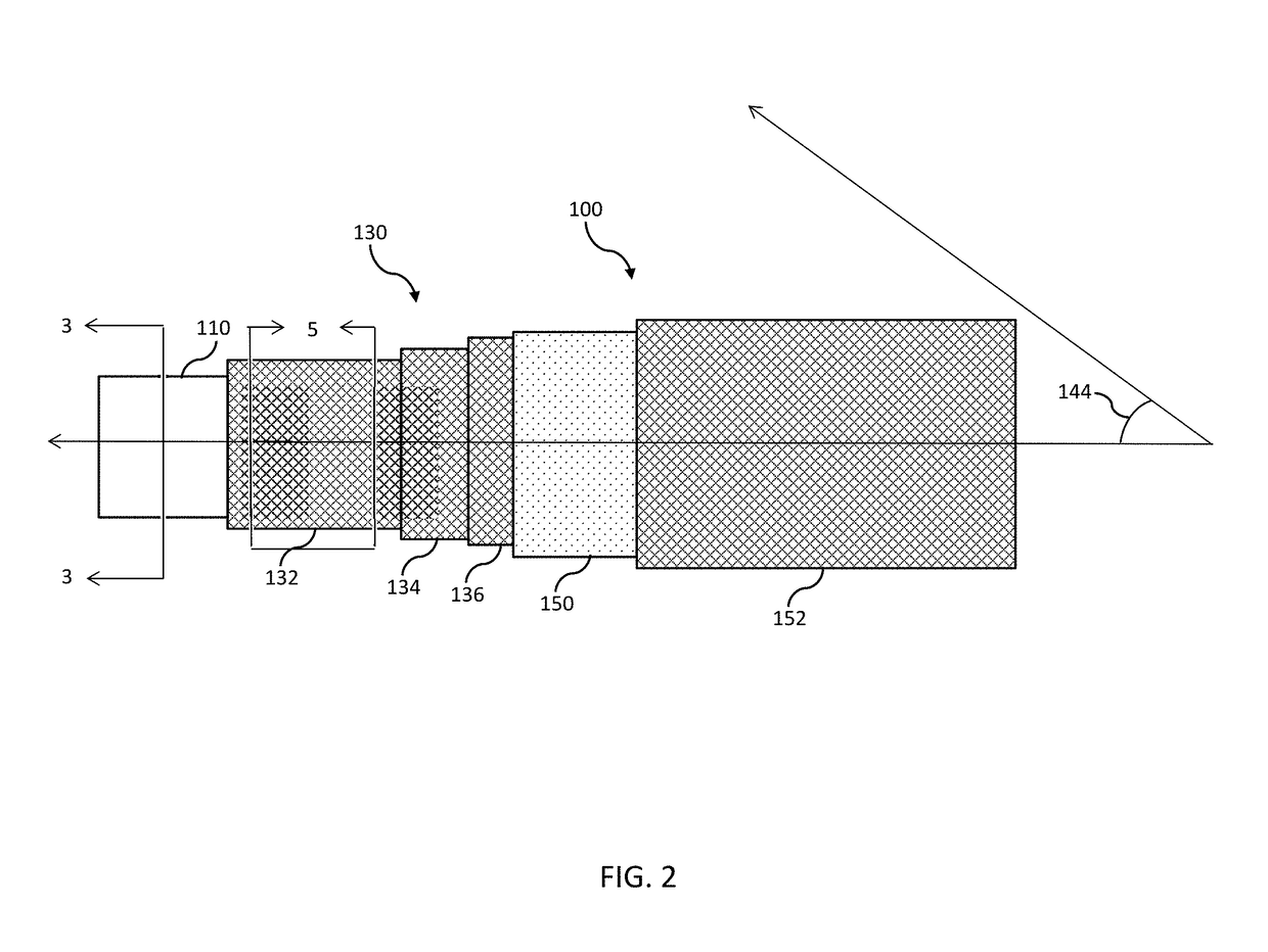
[0051, Embodiment 3, Embodiment 4, and Embodiment 5 demonstrated good performance after 20 cycles of testing. Each of Embodiment 2, Embodiment 3, Embodiment 4, and Embodiment 5 had an average propagation of less than about 11% and a maximum of less than about 24%. Each of the hoses tested for 20 cycles, had a relatively small percent difference of nominal breaking strength, measured according to ASTM D7269, between the support thread 140 of the fiber reinforcement layers 130. The difference of nominal breaking strength was less than about 25% such as, for example, less than about 5% in some examples.

[0052]Comparative Example, the High Tension Embodiment, Embodiment 5, Embodiment 13, Embodiment 15, and Embodiment 17 were tested for 120 cycles. After 120 cycles of testing, cross sections of the tested hoses were tested for micro-voids using fluorescent penetrant. The results of the testing are summarized below in Table 6 and Table 7.

TABLE 6PropagationPropagation Through WallThrough Wa...


PUM

PropertyMeasurementUnit
Fractionaaaaaaaaaa
Fractionaaaaaaaaaa
Fractionaaaaaaaaaa

Abstract

A hose can include an inner tube that can form a flow path and an inner fiber layer that can be formed around an outer surface of the inner tube. The hose can further include an intermediate fiber layer that can be formed around the inner fiber layer, and an intermediate fiber layer that can be formed around the inner fiber layer. An outer layer can be formed around the intermediate fiber layer. The inner fiber layer, the intermediate fiber layer, and the outer fiber layer can be formed from support thread applied with greater than about 10 pounds (lbs) of tension. The support thread of the inner fiber layer, the support thread of the intermediate fiber layer, and the support thread of the outer fiber layer can include aramid fibers.

Description

CROSS REFERENCED TO RELATED APPLICATION[0001]This application claims the benefit of U.S. Provisional Application No. 62 / 393,785, filed on Sep. 13, 2016 entitled “FIBER REINFORCED THERMOPLASTIC HOSES AND METHODS FOR FORMING THE SAME,” the contents of which are herein incorporated by reference.TECHNICAL FIELD[0002]This disclosure generally relates to thermoplastic hoses for conveying fluid and, more specifically, to thermoplastic hoses for conveying hydraulic fluids, oil, and fuel.BACKGROUND[0003]Hoses can be utilized to provide a flexible mechanism for conveying fluid between two or more components. Thermoplastic hoses have many applications including industrial, hydraulic, and aircraft applications. For example, thermoplastic hoses can be utilized to convey pressurized fuel, oil, hydraulic fluid, or the like. Accordingly, the interior of thermoplastic hoses can be exposed to deleterious fluids at relatively high pressures. Additionally, thermoplastic hoses can be subjected to relati...

Claims


Application Information

Patent Timeline
IPC IPC(8): F16L11/08
CPCF16L11/087F16L11/125F16L11/127B32B1/08B32B5/26B32B9/04B32B9/047B32B15/043B32B15/14B32B15/20B32B25/10B32B27/12B32B27/322B32B2262/0269B32B2307/202B32B2307/50B32B2597/00B32B1/00
Inventor KOTCHAROV, SERGEY Y.
Owner EATON INTELLIGENT POWER LIMITED
Why Eureka
Try Eureka