Method and apparatus for online condition monitoring of spent nuclear fuel dry cask storage systems

a technology of spent nuclear fuel, which is applied in the direction of instruments, nuclear elements, greenhouse gas reduction, etc., can solve the problems of limited types of abnormalities detected by manual inspection, limited deployment of means to online monitor dry cask storage system, and associated uncertainties of simulations

Inactive Publication Date: 2018-03-15
BATTELLE ENERGY ALLIANCE LLC
View PDF0 Cites 2 Cited by
  • Summary
  • Abstract
  • Description
  • Claims
  • Application Information

AI Technical Summary

Problems solved by technology

However, simulations are associated with uncertainties, especially because of the lack of information on the dry cask storage system's actual internal environment.
Manual inspections detect limited types of abnormalities and do not facilitate a prompt warning and response.
Deployed means to online monitor dry cask storage systems are limited to basic pressure, temperature, or radiation sensors to generate an overall alarm for abnormalities.
However, this type of monitoring is not sufficient or comprehensive.
In situ efforts have several limitations that hinder their near-term deployment.
Some of these limitations are the narrowness of the space between the canister and the concrete cask, which constrains the size of in situ instruments and their supporting structures; the lack of direct access to the narrow space, which hinders the installation and wiring of the instruments; the harsh environment of the narrow space, such as high radiation, temperature and air speed, which necessitates very robust and tolerant instruments; and the localized nature of placement of in situ instruments on the canister surface, which provides location-specific information only and can degrade the canister performance at that location.
Current ex situ efforts provide limited information on the status of the dry cask storage system, and the information is biased towards the measurement position.
However, because of the size of a concrete cask, this device will give an indication that is biased towards the installation position.

Method used


Image

  • Method and apparatus for online condition monitoring of spent nuclear fuel dry cask storage systems
  • Method and apparatus for online condition monitoring of spent nuclear fuel dry cask storage systems
  • Method and apparatus for online condition monitoring of spent nuclear fuel dry cask storage systems

Examples


example 1

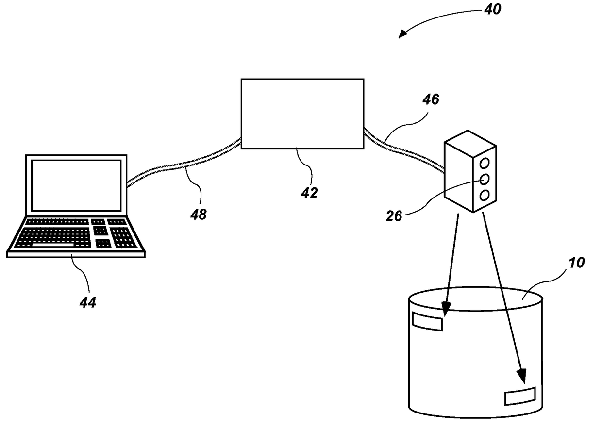
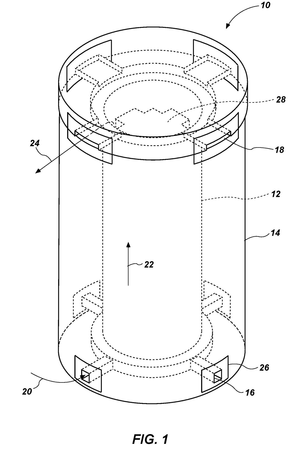
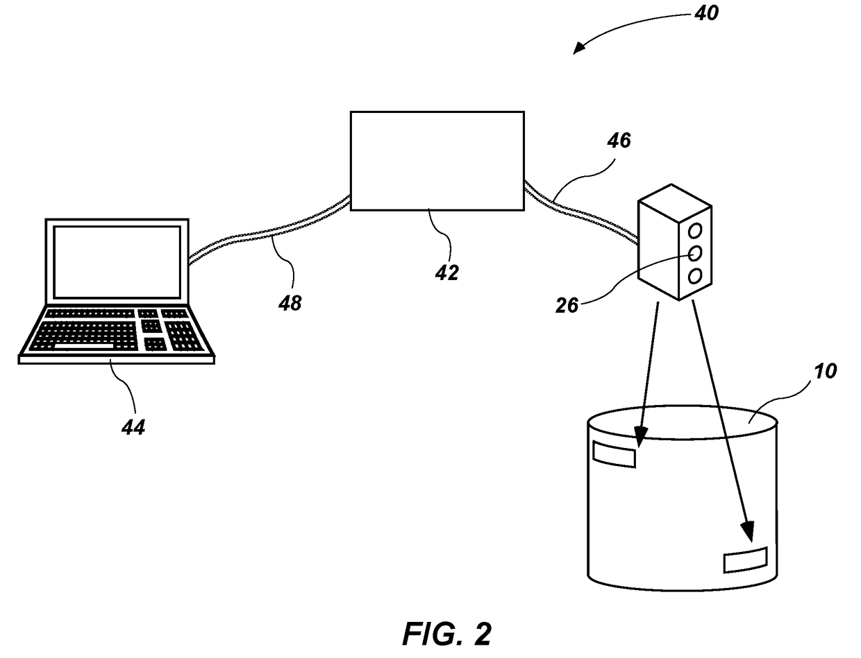
[0047]Since the device measures the flow rate, temperature and air composition in and out of the dry cask, the steady state dissipated heat into air can be determined using:

Q=Σi=1i=Noutmi,outTi,outCi,p,out−Σi=1i=Ninmi,inTi,inCi,p,in−EE−DE+OE  (1)

where Q is the dissipated heat rate, Nout is the number of outlet vents, Nin is the number of inlet vents, mi is the mass flow rate at vent i, Cp is the specific heat capacity, T is the temperature, FE is the rate of escaped energy through the overpack surface and ground, DE is the rate of energy that is absorbed and stored, and OE is the rate of other sources of energy including radiation and chemical interactions. Most of the heat will be transferred to the flowing air. A small portion will be transferred through the overpack. A very small portion will be transferred back into the dry cask, and a negligible amount of heat is lost or generated through chemical and radiation interactions. After years in spent fuel pools, the decay heat profi...

example 2

[0049]Since the device measures the flow rate and characteristics of air flowing in and out of a canister, the net flow rate of air can be determined as:

F=Σi=1i=Nout(mi,out−di,out−ei,out)−Σi=1i=Nin(mi,in−di,in−ei,in)  (2)

where di is the solid impurities concentration in air, and ei is the concentration of other elements in air. The net flow rate of air can be used for several performance indicators. For instance, a steady increase of the net air flow indicates that an additional source of flow has been introduced, possibly a canister helium leak or overpack leak. This measurement can be correlated with other measurements to determine the cause. A steady accumulated negative net flow rate indicates an overpack leak. A sudden reduction of the flow rate in multiple vents could indicate that an obstacle blocked the flow path.

example 3

[0050]The radiation level measurement at each vent can be interpreted by itself or correlated with other measurements for a performance indication. For example, an increase of the ratios of radiation level and heat dissipation in one vent to other vents points towards the radial location of a canister leakage. An increase of radiation level at an outlet and inlet vent indicates an external source of radiation (e.g., failure of an adjacent dry cask). An increase of radiation at the inlet vents only indicates fuel relocation.


PUM


Abstract

A method and apparatus for online condition monitoring of a spent nuclear fuel dry cask storage system. The method comprises monitoring physical parameters of air flowing through inlet vents and outlet vents of a system and observing successive measurements of the parameter for deviations from the baseline to determine if the condition of the system has changed. The parameters may include temperature, pressure, density, mass and volumetric flow rate, nuclear radiation, impurities, humidity, salt content, acidity, chemistry, and fission product gases. The information may then be used directly or to develop an accumulation profile. The data may also be used in modeling or other simulations and to establish condition change signatures. The apparatus includes sensors placed over inlet and outlet vents, sensor interfacing hardware connected to the sensors, and a computer connected to the hardware to acquire, display, and analyze the sensor data and to display the status of the system.

Description

CROSS-REFERENCE TO RELATED APPLICATIONS[0001]This application claims the benefit of U.S. Provisional Patent Application Ser. No. 62 / 394,058, filed Sep. 13, 2016, the disclosure of which is hereby incorporated herein in its entirety by this reference.STATEMENT REGARDING FEDERALLY SPONSORED RESEARCH OR DEVELOPMENT[0002]This invention was made with government support under Contract Number DE-AC07-05ID14517 awarded by the United States Department of Energy. The government has certain rights in the invention.TECHNICAL FIELD[0003]The invention, in various embodiments, relates to a method and apparatus for online condition monitoring of spent nuclear fuel dry cask storage systems. More specifically, embodiments of the invention relate to a method and apparatus for continuous ex situ monitoring of spent nuclear fuel in dry cask storage systems by measuring various physical parameters of air flow into and out of the cask system.BACKGROUND[0004]Dry cask storage systems are the main alternativ...

Claims


Application Information

Patent Timeline
Patent Type & Authority Applications(United States)
IPC IPC(8): G21C17/06G21F5/06G01T1/167
CPCG21C17/06G21F5/06G01T1/167G01M3/38G08C2201/10H02J7/0055G21F5/10G21F5/12G21F5/125H04Q9/00Y02E30/30H02J2207/40
Inventor AL RASHDAN, AHMAD Y
Owner BATTELLE ENERGY ALLIANCE LLC
Why Eureka
Try Eureka