Ude-based robust droop control for parallel inverter operation

a parallel inverter and robust technology, applied in the direction of single network parallel feeding arrangement, power conversion system, electrical apparatus, etc., can solve the problems of inability to handle system disturbances, inaccurate reactive power sharing, and traditional droop control strategies. achieve accurate proportional load sharing

Active Publication Date: 2018-03-15
TEXAS TECH UNIV SYST
View PDF11 Cites 13 Cited by
  • Summary
  • Abstract
  • Description
  • Claims
  • Application Information

AI Technical Summary

Benefits of technology

[0007]It is another aspect of the disclosed embodiments to provide for a control device, system, and method for parallel operated inverters to achieve accurate proportional load sharing.
[0008]It is another aspect of the disclosed embodiments to provide for an improved droop control strategy capable of handling system disturbances while allowing for accurate proportional load sharing among parallel-operated inverters.

Problems solved by technology

This results in inaccurate reactive power sharing—an important aspect of power sharing performance.
Traditional droop control strategies are also unable to handle system disturbances, such as large or quick load changes, variations in output impedances, and fluctuating DC-link voltages.

Method used


Image

  • Ude-based robust droop control for parallel inverter operation
  • Ude-based robust droop control for parallel inverter operation
  • Ude-based robust droop control for parallel inverter operation

Examples


case 1

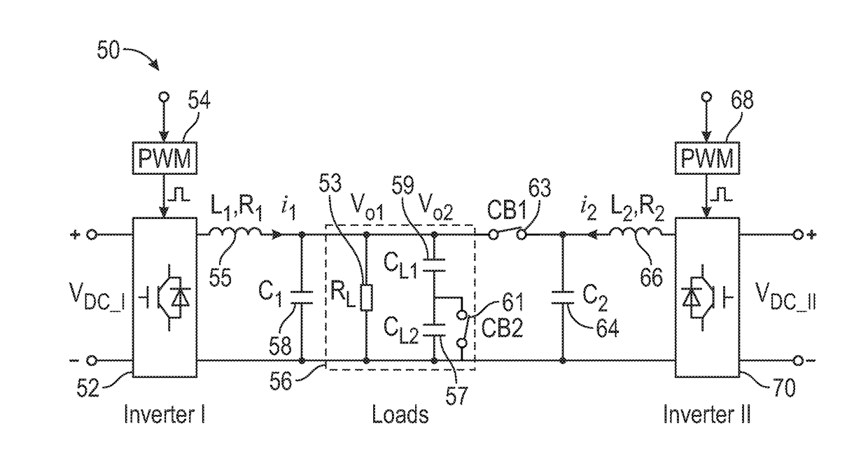
[0072, or the nominal case, involves a situation in which initially the load is connected to Inverter I only, and Inverter II is connected to the load at t=2 s by turning the switch CB1 ON. At t=6 s, the Inverter II is disconnected. The system response curves with the proposed UDE-based robust droop control of equations (16) and (6) are shown in FIGS. 5A-5F. Initially, only Inverter I is connected to the load with switch CB1 OFF and switch CB2 ON. The frequency drop is shown in graph 88 of FIG. 5D due to the effect of positive real power as shown in graph 82 of FIG. 5A. The voltage drop as shown in graph 89 is high in the single-inverter mode, and the negative drop direction is due to the effect of negative reactive power as shown in graph 84 in FIG. 5B with the capacitive load. At t=2 s, the switch CB1 is turned ON, and Inverter II is connected to the load. The load voltage Vo2 is measured by Inverter II for voltage synchronization with the zero-crossing technique. Some small spike...

case 2

[0075 or the disturbance rejection case: In this case, three disturbances are considered: i) change of the output impedance; ii) change of the DC-link voltage; and iii) change of the load. FIGS. 6A-6D illustrate a group of graphs 102, 104, 106, 108, 110, 112, 114, 116, 118, 120, 122, and 124 depicting transient experimental results under different scenarios, in accordance with example embodiments. Initially, the load is connected to the Inverter I only, with switch CB1 OFF and switch CB2 ON. Inverter II is connected to the load at t=2 s by turning switch CB1 ON. At t=6 s, three disturbances are applied to the system, separately. At t=10 s, Inverter II is disconnected.

[0076]i) Change of the output impedance: For change of the output impedance, a virtual output impedance Rv1=3Ω with feedback current is added in Inverter I at t=6 s. This virtual output impedance mimics the disturbance from the variation of output impedance.

[0077]The experimental results are shown in the left column of ...


PUM


Abstract

A control system and method include a control strategy and a UDE (Uncertainty and Disturbance Estimator)-based controller incorporated into the control strategy to achieve proportional load sharing for parallel-operated inverters. The UDE-based controller regulates the reactive power against the output generated by a reactive power reference unit according to the load voltage to generate the amplitude of the control voltage. The conventional droop method regulates real power to generate the phase of the control voltage. As a result, the model uncertainties (e.g., parameter drifts and uncertain output impedance), and system disturbances (e.g., fluctuating DC-link voltage and load change) can be estimated and compensated for accurate load sharing.

Description

CROSS-REFERENCE TO PROVISIONAL APPLICATION[0001]This nonprovisional patent application claims the benefit of and priority under 35 U.S.C. § 119(e) to U.S. Provisional Patent Application Ser. No. 62 / 394,303, filed on Sep. 14, 2016, entitled “UDE-Based Robust Droop Control for Parallel Inverter Operation.” U.S. Provisional Patent Application Ser. No. 62 / 394,303 is incorporated herein by reference in its entirety.TECHNICAL FIELD[0002]Embodiments are related to control devices for parallel operated inverters to achieve accurate proportional load sharing. Embodiments are also related to microgrid, smart grid, and renewable energy applications. Embodiments further relate to UDE (Uncertainty and Disturbance Estimator)-based control methods.BACKGROUND[0003]The use of renewable energy technologies, such as wind and solar energy, is vastly increasing. With their increasing use, their incorporation into power grids is essential for taking advantage of the energy they produce. The incorporation...

Claims


Application Information

Patent Timeline
Patent Type & Authority Applications(United States)
IPC IPC(8): H02J3/46H02M7/5395
CPCH02J3/46H02M7/5395H02M7/493H02M1/0025
Inventor REN, BEIBEIWANG, YEQINZHONG, QING-CHANG
Owner TEXAS TECH UNIV SYST
Why Eureka
Try Eureka