Cleaning brush for electrostatographic apparatus

a technology for electrostatographic equipment and cleaning brushes, which is applied in the direction of electrographic process equipment, instruments, optics, etc., can solve problems such as complicated voltage control, and achieve the effects of improving the robustness of fiber variations, excellent cleaning performance, and reducing the tendency to draw curren

Active Publication Date: 2012-01-05
EASTMAN KODAK CO
View PDF9 Cites 7 Cited by
  • Summary
  • Abstract
  • Description
  • Claims
  • Application Information

AI Technical Summary

Benefits of technology

[0009]It is surprising that with the insertion of a non-conductive layer, the brush continues to provide excellent cleaning performance. Further, the brushes of the current invention have improved robustness to variations in the fiber providing the advantage of lower tendency to draw current. This advantage provides simpler control strategies and lower systems cost. An additional advantage of reduced sensitivity to the fiber is that waste is avoided when the fiber properties vary. Yet another advantage of the current invention is reduced sensitivity to environmental variations such as increased humidity.

Problems solved by technology

Current draw by the brush in inductively coupled fiber cleaning brushes of the prior art employing a conductive backing has been found to complicate voltage control of the detone roller due to excessive conductivity.

Method used


Image

  • Cleaning brush for electrostatographic apparatus
  • Cleaning brush for electrostatographic apparatus
  • Cleaning brush for electrostatographic apparatus

Examples


example 1

[0042]Brushes were prepared substantially as in Comparative Example 2 except that the conductive coating was replaced with a non-conductive coating (RHOPLEX natural latex rubber from Heveatex Corp.) having a resistivity greater than 1012 ohm-cm, at a coverage of 0.0076 g / cm2.

example 2

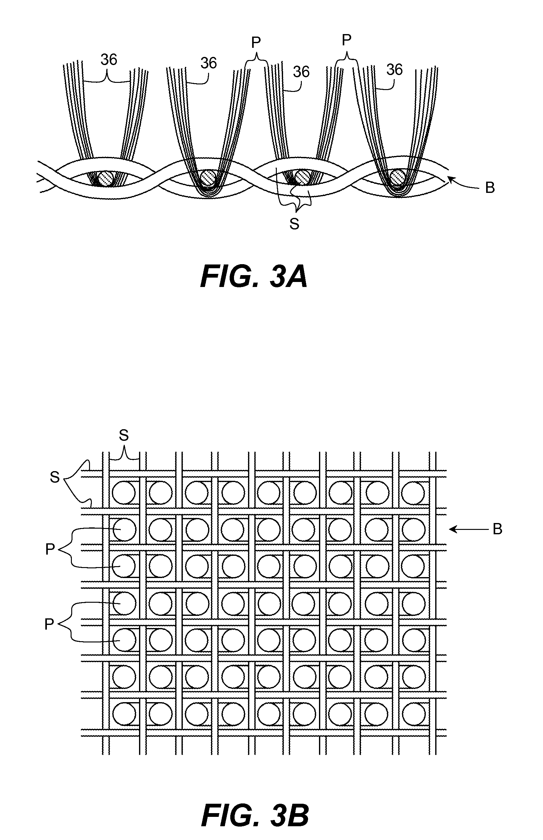
[0043]Brushes were prepared substantially as in Example 1 except that following the coating of the non-conductive coating, a conductive coating (carbon loaded latex RA-512-16A-Black No. 1 from Heveatex Corp.) having a resistivity less than 109 ohm-cm, at a coverage of 0.003 g / cm2, was further applied. Scanning electron microscopy shows that the first non-conductive coating 37 penetrates the fiber bundles, coats the fibers, and separates the subsequently coated conductive layer 38 from the fibers (FIG. 4C).

example 3

[0044]The tips of finished brushes of Comparative Example 2 were coated with a heptane solvent solution of PICOTEX vinyl toluene / alpha-methylstyrene copolymer (from Hercules) to seal the conductive core that is otherwise exposed when the brushes are sheared during manufacturing.

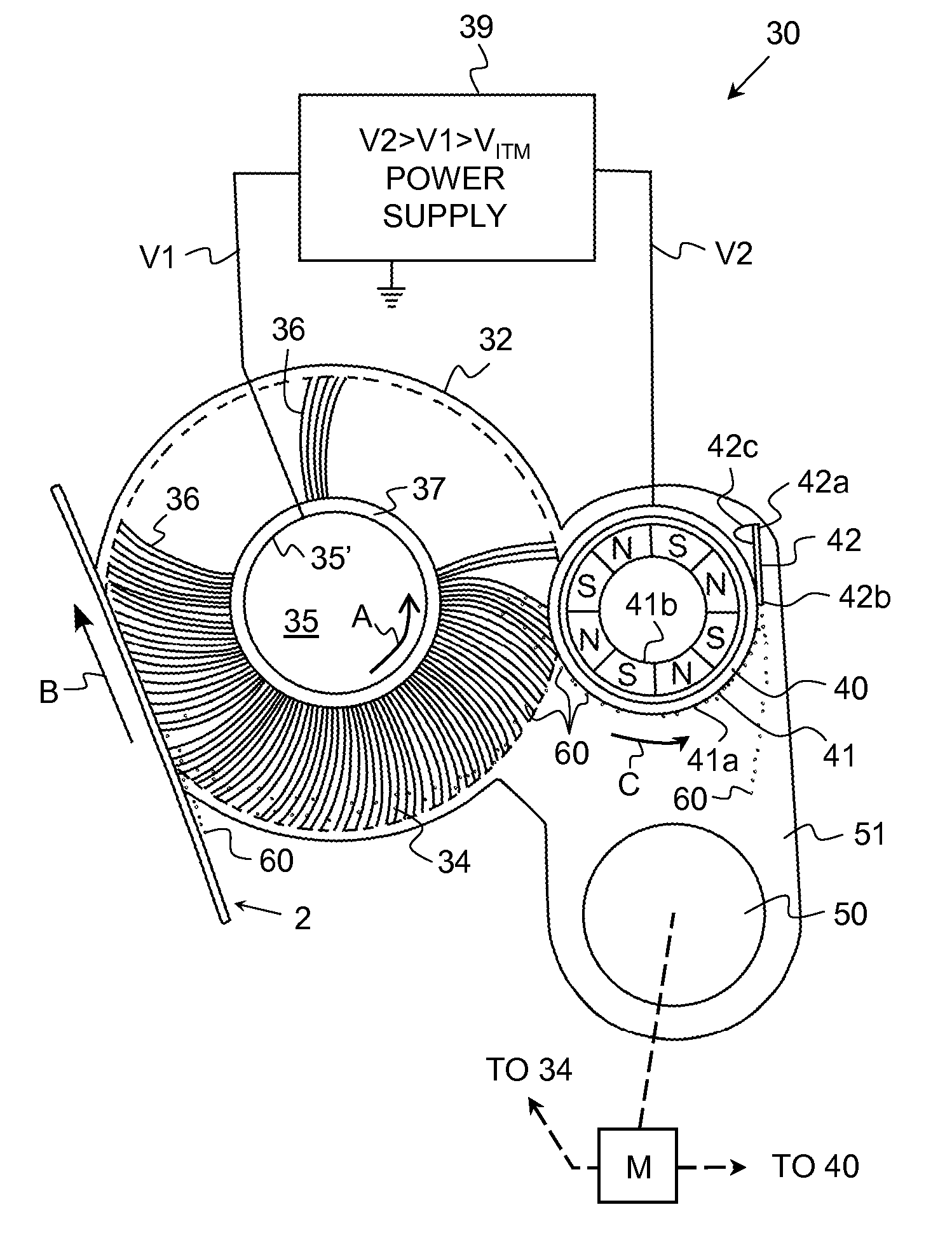
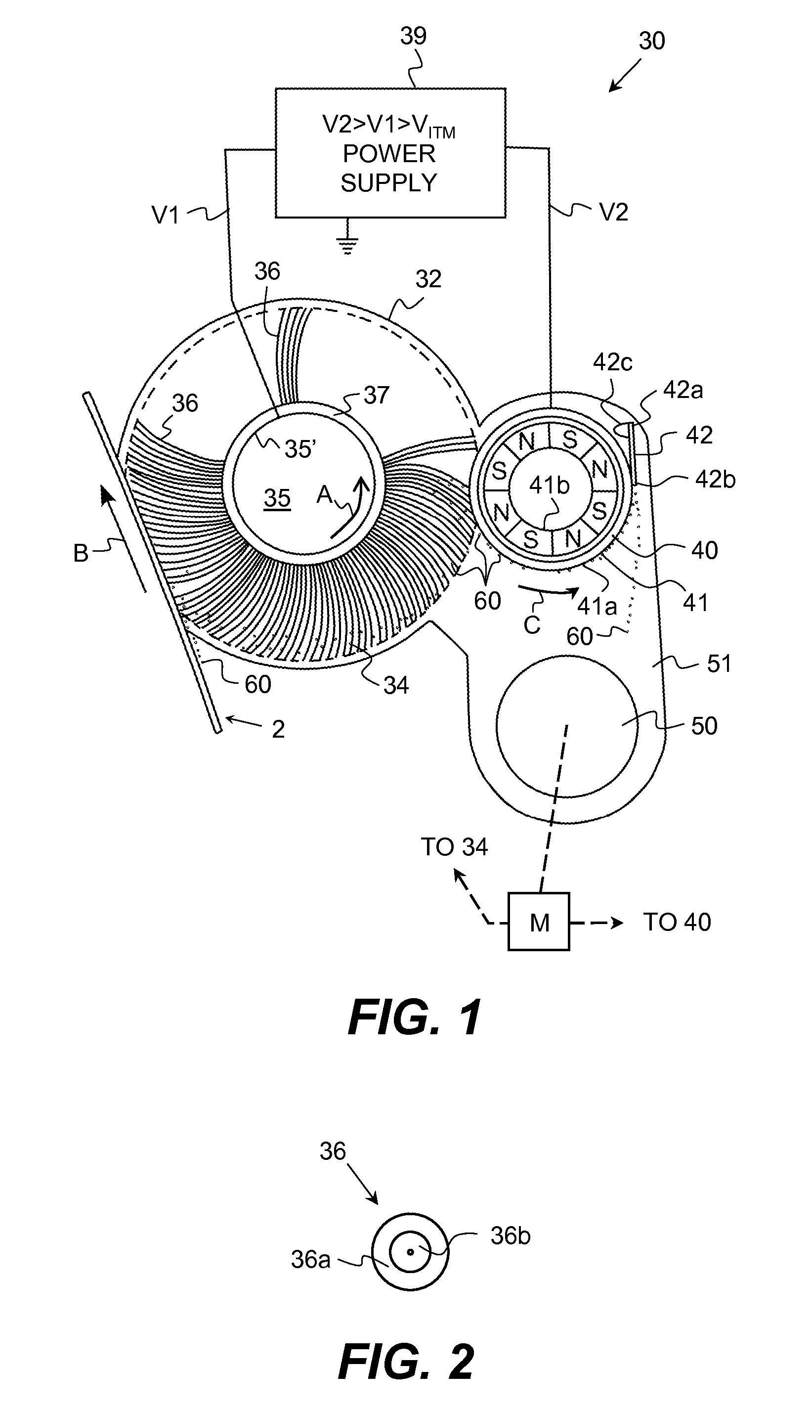
[0045]Brush conductivity was evaluated in the following manner: A test fixture was constructed consisting of a cleaning station (with cleaning brush), cleaning station motor power supply, and two Cor-A-Trol's. One Cor-A-Trol was used to apply a constant 300V to the cleaning brush. The second Cor-A-Trol was used to apply a voltage to the detone roller, and to measure the current draw between the cleaning brush and detone roller. With the cleaning station motor running, the current draw was measured on the detone roller Cor-A-Trol at 100V increments starting a 0V and ending when the current draw exceeded the Cor-A-Trol ability to sink the current, or at the pre-determined limit of 1 KV.

[0046]FIG. 6 illustrates ...


PUM


Abstract

A cleaning brush for use in an electrostatographic imaging apparatus, including a plurality of individual electrically conductive fibers secured to a brush core and having fiber tips relatively remote from the brush core, wherein the cleaning brush includes an electrically conductive plane at a surface of the brush core, or between a surface of the brush core and the electrically conductive fibers, effective for inducing an electrical potential to the conductive fibers when an electrical potential is applied to the electrically conductive plane, and at least one of a relatively non-conductive layer electrically insulating the conductive plane from the conductive fibers, or electrically insulating coatings on tips of the electrically conductive fibers remote from the brush core. The insulative, or non-conductive, layer between the fibers and the conductive plane of the brush prevent excessive current draw.

Description

FIELD OF THE INVENTION[0001]The present invention relates to a cleaning member for an electrostatographic imaging apparatus and methods and in particular to cleaning remnant toner and magnetic carrier particles from a toner bearing member in such an apparatus.DESCRIPTION RELATIVE TO THE PRIOR ART[0002]In electrostatographic imaging apparatus commonly used today, a photoconductive insulating member is typically charged to a uniform potential and thereafter exposed to a light image of an original document to be reproduced. The exposure discharges the photoconductive insulating surface in exposed or background areas and creates an electrostatic latent image on the member which corresponds to the image contained within the original document. Alternative, a light beam may be modulated and used to selectively discharge portions of the charged photoconductor surface to record the desired information thereon. Typically, such a system employs a laser beam or LED printhead. Subsequently, the ...

Claims


Application Information

Patent Timeline
Patent Type & Authority Applications(United States)
IPC IPC(8): G03G21/00
CPCG03G2215/1661G03G21/0035
Inventor PICKERING, JERRY A.JONES, KURT E.LAMBERT, PATRICK M.ALEXANDROVICH, PETER S.
Owner EASTMAN KODAK CO
Why Eureka
Try Eureka