
Joint actuator, and joint structure of leg-supporting robot comprising same

a joint structure and actuator technology, applied in the direction of mechanical equipment, manufacturing tools, gearing, etc., can solve the problems of increasing the output torque of the electric motor, and increasing the degree of freedom of movement of the user who wears the leg-supporting robot. , to achieve the effect of more flexibly using, reducing artificial control of mechanical friction or adjustmen

Active Publication Date: 2018-03-22
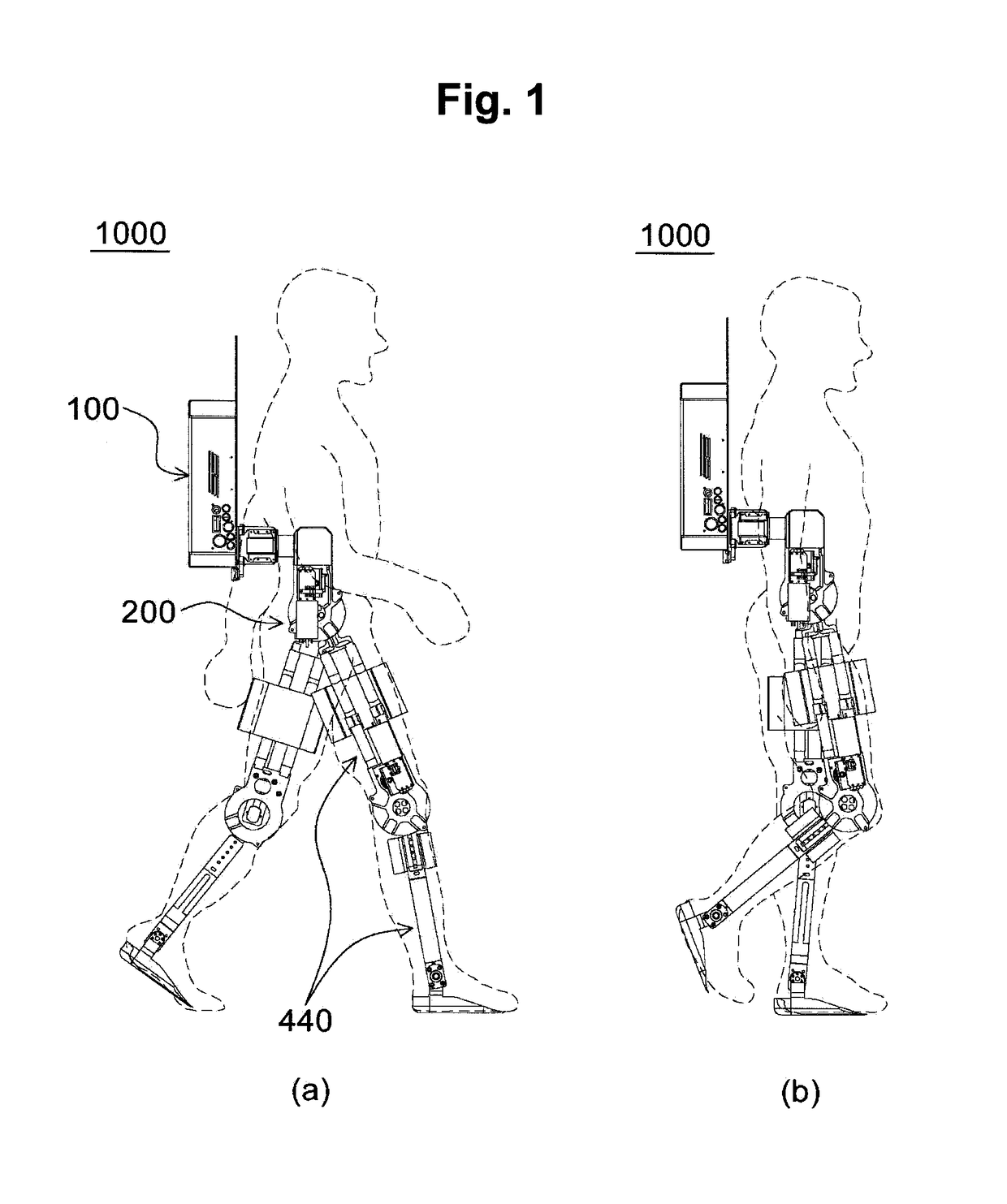
ANGEL ROBOTICS CO LTD
View PDF9 Cites 17 Cited by
  • Summary
  • Abstract
  • Description
  • Claims
  • Application Information

AI Technical Summary

Benefits of technology

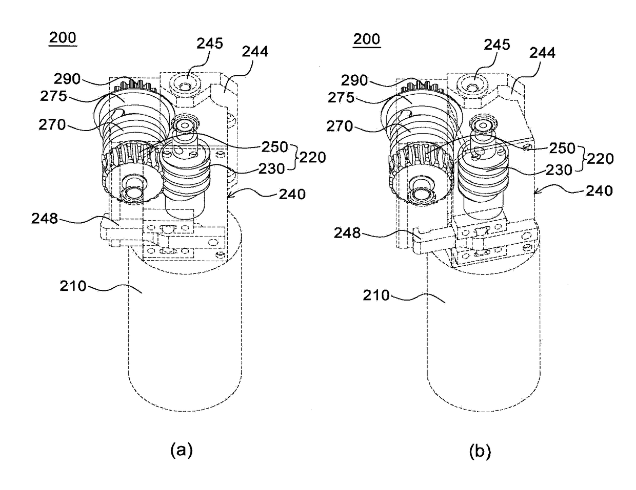
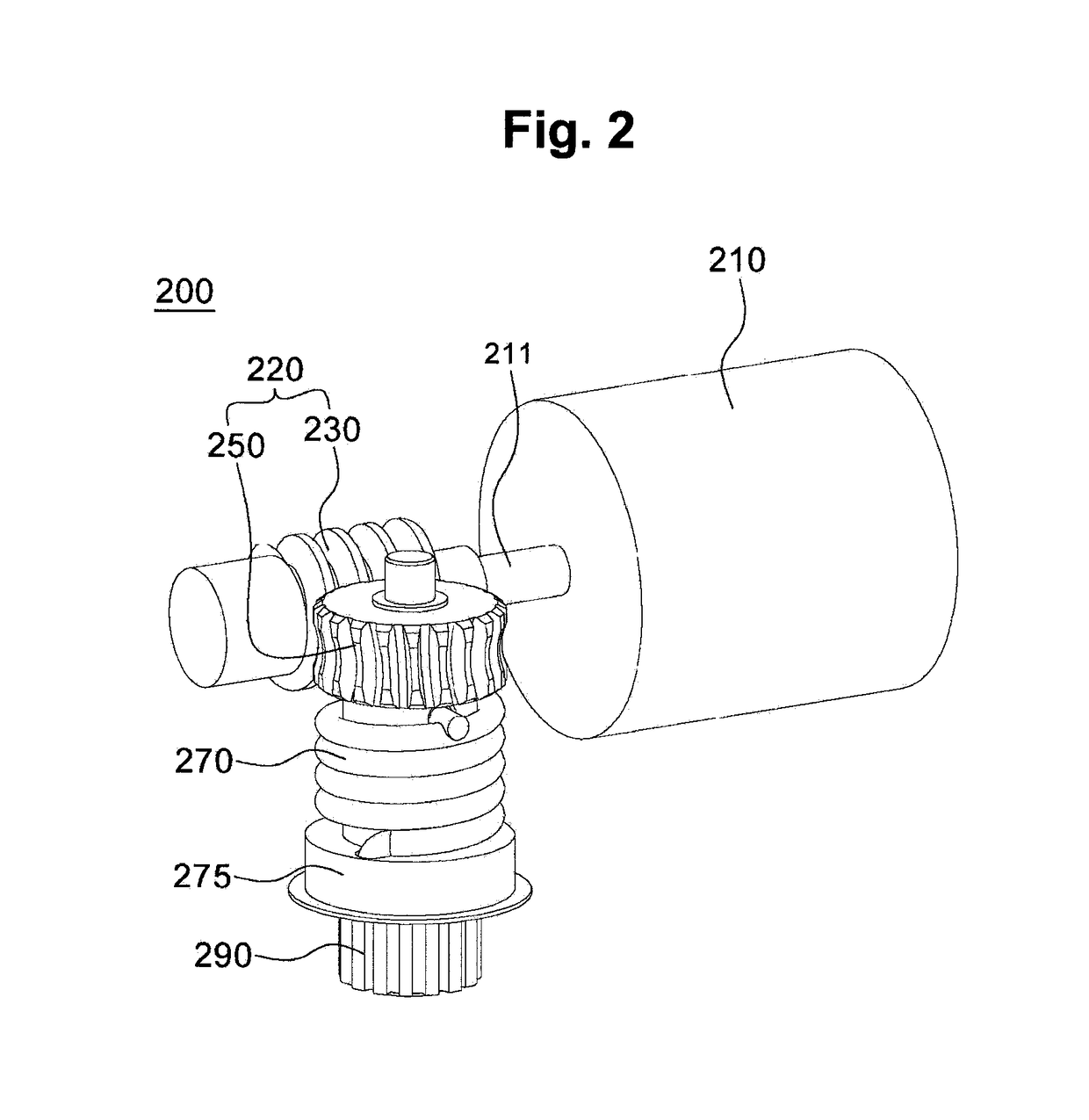
The present invention is a joint actuator and joint structure for a leg-supporting robot that reduces mechanical friction and allows for flexible movement of the user. The actuator includes an elastic body to transfer power from the motor to the joint part, and different types of elastic bodies with different degrees of hardness can be used to provide different turn forces for different devices and users. Additionally, the actuator allows for selective engagement of gear parts, increasing the degrees of freedom of movement for the user and allowing for more flexible use of the leg-supporting robot.

Problems solved by technology

However, when the speed reducer is used in the electric motor, the output torque of the electric motor increases according to a gear ratio but a degree of mechanical friction that a user may feel is not low due to a friction force generated when a plurality of gears are rotated while being engaged with each other.
Due to the mechanical force generated by the plurality of gears, the user would feel the sense of irritation and discomfort when the user wears the leg-supporting robot.
However, although providing a sufficient degree of driving power for joints and reducing the mechanical friction to secure the user's flexible movement are contrary to each other in terms of purpose or function, there should be a trade-off between them.

Method used


Image

  • Joint actuator, and joint structure of leg-supporting robot comprising same
  • Joint actuator, and joint structure of leg-supporting robot comprising same
  • Joint actuator, and joint structure of leg-supporting robot comprising same

Examples


Embodiment Construction

Technical Problem

[0010]The present invention is directed to a joint actuator which includes an elastic component and is thus capable of reducing or adjusting mechanical friction which may be generated at a joint part of a leg-supporting robot according to a situation or an external environment, and a joint structure of a leg-supporting robot including the joint actuator.

[0011]The present invention is also directed to a joint actuator in which gear parts may be selectively engaged with each other to improve a degree of freedom of movement of a joint part of a leg-supporting robot, and a joint structure of a leg-supporting robot including the joint actuator.

Technical Solution

[0012]According to an aspect of the present invention, there is provided a joint actuator comprising: a motor; a first gear part configured to change a direction of a rotational driving force applied by the motor and reduce speed of the rotational driving force so as to increase and apply the rotational driving fo...


PUM


Abstract

The present invention relates to a joint actuator, and a joint structure of a leg-supporting robot using the joint actuator. The joint actuator can reduce or control mechanical friction which a user can feel during use thereof, and is designed so as to be able to be flexibly driven since selective engagement of a gear part is possible.

Description

TECHNICAL FIELD[0001]The present invention relates to a joint actuator and a joint structure of a leg-supporting robot including the same. More specifically, the present invention relates to a joint actuator which is capable of reducing or adjusting mechanical friction that a user may feel during use thereof and which is designed to be flexibly driven through selective engagement of gear parts, and a joint structure of a leg-supporting robot using the joint actuator.BACKGROUND ART[0002]Robots supporting body parts of elderly people growing due to an aging society and persons who acquired disability due to various accidents have been introduced.[0003]Such devices supporting movement of those with impaired mobility have been continuously developed and commercialized. A leg-supporting robot supporting movement of a malfunctioning leg is a representative example of such devices.[0004]The leg-supporting robot is a robot which provides joint torque to support weak legs of the disabled, th...

Claims


Application Information

Patent Timeline
IPC IPC(8): B25J13/04B25J9/08
CPCB25J13/04B25J9/08F16H3/20B25J19/00A61H1/0255B25J9/0006B25J9/102B25J17/0208A61H1/024A61H1/0244A61H3/00A61H2201/1215A61H2201/1463A61H2201/164A61H2201/165A61H2201/1671A61H2201/50A61H2201/5053A61H2201/5058A61H2203/0406A61H2205/10
Inventor WOO, HAN-SEUNGNA, BYEONG-HUNKONG, KYOUNG-CHULKIM, HYUCK-BAE
Owner ANGEL ROBOTICS CO LTD
Learn More