Eureka AIR delivers breakthrough ideas for toughest innovation challenges, trusted by R&D personnel around the world.

Hydraulic excavator drive system

a drive system and hydraulic technology, applied in mechanical machines/dredgers, fluid-pressure actuators, fluid-pressure actuators, etc., can solve the problems of high cost and complex configuration of the drive system b>100/b>, and achieve the reduction of the necessary motive force for swinging the swinging unit, prevent cavitation, and simple structure

Active Publication Date: 2018-03-22
KAWASAKI HEAVY IND LTD
View PDF28 Cites 7 Cited by
  • Summary
  • Abstract
  • Description
  • Claims
  • Application Information

AI Technical Summary

Benefits of technology

The present invention is a hydraulic excavator drive system that prevents cavitation in a cylinder that swings an arm or bucket, even at a low cost. This helps to maintain the efficiency and performance of the excavator.

Problems solved by technology

Thus, the configuration of the drive system 100 is complex, and the cost thereof is high.

Method used


Image

  • Hydraulic excavator drive system
  • Hydraulic excavator drive system
  • Hydraulic excavator drive system

Examples


embodiment 1

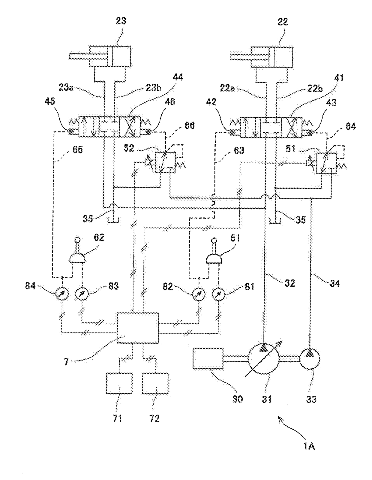
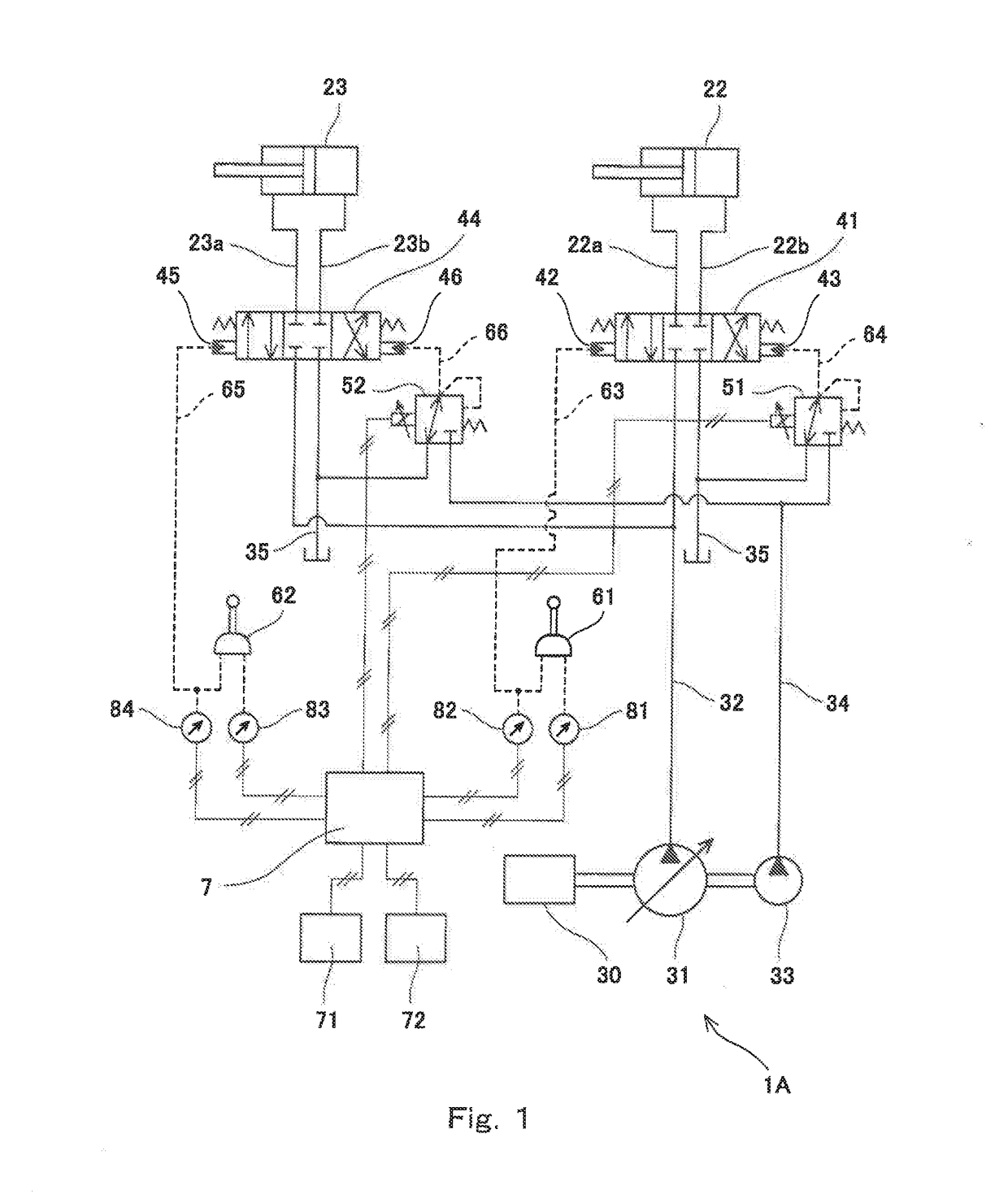
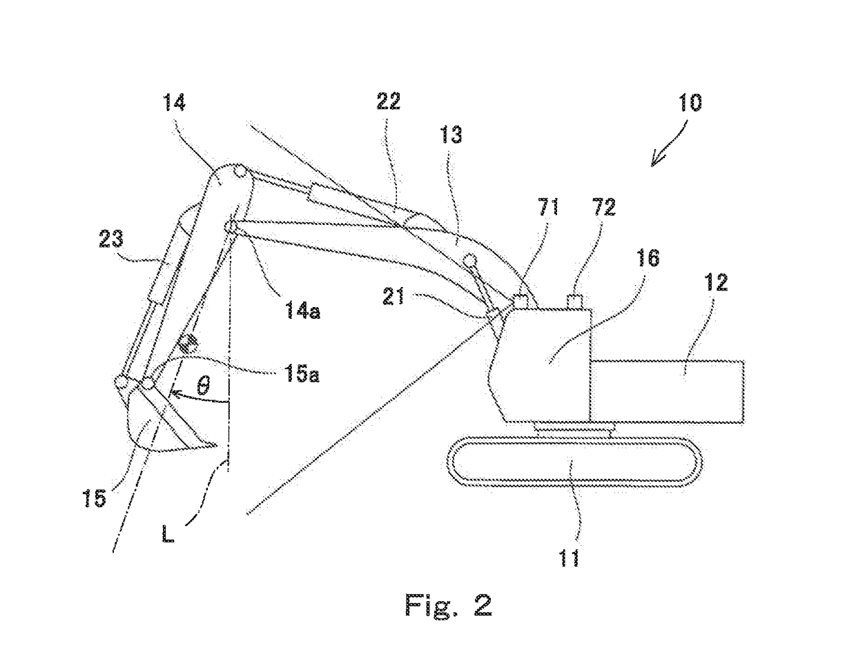
[0027]FIG. 1 shows a hydraulic excavator drive system 1A according to Embodiment 1 of the present invention. FIG. 2 shows a hydraulic excavator 10, in which the drive system 1A is installed.

[0028]The hydraulic excavator 10 shown in FIG. 2 is a self-propelled excavator, and includes a running unit 11. The hydraulic excavator 10 further includes: a turning unit 12 turnably supported by the running unit 11; and a boom 13, which is raised and lowered relative to the turning unit 12. An arm 14 is swingably coupled to the distal end of the boom 13, and a bucket 15 is swingably coupled to the distal end of the arm 14. The turning unit 12 includes a cabin 16, in which an operator's seat is set.

[0029]As shown in FIG. 1, the drive system 1A includes, as hydraulic actuators, a pair of right and left running motors and a turning motor (which are not shown), a boom cylinder 21 (see FIG. 2), an arm cylinder 22, and a bucket cylinder 23. The boom cylinder 21 raises and lowers the boom 13. The arm ...

embodiment 2

[0064]Next, a hydraulic excavator drive system 1B according to Embodiment 2 of the present invention is described with reference to FIG. 7.

[0065]In the present embodiment, each of the arm operation device 61 and the bucket operation device 62 is an electrical joystick that outputs an electrical signal to the controller 7 as an operation signal. For this reason, the second pilot port 42 of the arm control valve 41 is connected to an arm solenoid proportional valve 53 by the arm pushing pilot line 63, and the second pilot port 45 of the bucket control valve 44 is connected to a bucket solenoid proportional valve 54 by the bucket-out pilot line 65. It should be noted that FIG. 7 shows only part of signal lines for simplifying the drawing.

[0066]In the present embodiment, the control based on the upper limit pressure PL, which is described in Embodiment 1, may be performed only at the time of arm crowding operation or only at the time of bucket-in operation. Alternatively, in the present...


PUM


Abstract

A hydraulic excavator drive system includes: a control valve for a cylinder that swings a swinging unit; an operation device that outputs an operation signal in accordance with an inclination angle of an operating lever when receiving a first operation of moving the swinging unit closer to a cabin or a second operation of moving the swinging unit farther from the cabin; a solenoid proportional valve connected to a first pilot port of the control valve, the first pilot port being intended for the first operation; and a controller that, when the operation device receives the first operation, controls the solenoid proportional valve such that: a pilot pressure outputted from the solenoid proportional valve is proportional to the operation signal outputted from the operation device until the pilot pressure reaches an upper limit pressure; and the closer the swinging unit to the cabin, the higher the upper limit pressure.

Description

BACKGROUND OF THE INVENTION1. Field of the Invention[0001]The present invention relates to a hydraulic excavator drive system.2. Description of the Related Art[0002]Generally speaking, a hydraulic excavator includes: a boom that is raised and lowered relative to a turning unit; an arm swingably coupled to the distal end of the boom; and a bucket swingably coupled to the distal end of the arm. A drive system installed in such a hydraulic excavator includes, for example, a boom cylinder that raises and lowers the boom, an arm cylinder that swings the arm, and a bucket cylinder that swings the bucket. These hydraulic actuators are supplied with hydraulic oil from a pump via control valves.[0003]For example, Japanese Laid-Open Patent Application Publication No. H05-187409 discloses a hydraulic excavator drive system 100 shown in FIG. 8. In the drive system 100, the supply and discharge of hydraulic oil to and from an arm cylinder 110 is controlled by a control valve 150. The control val...

Claims


Application Information

Patent Timeline
IPC IPC(8): E02F9/22
CPCE02F9/226E02F9/2228F15B2211/30525F15B2211/329F15B2211/20576F15B2211/40576E02F3/42E02F9/22E02F3/435E02F9/2285E02F9/2296
Inventor KONDO, AKIHIROKATO, TAKEHISA
Owner KAWASAKI HEAVY IND LTD
Why Eureka
Eureka Blog
Learn More