Power amplifying converter

a technology of power amplifying converters and converters, applied in amplifiers, amplifiers with semiconductor devices/discharge tubes, amplifiers with coupling networks, etc., to achieve the effects of reducing the overall area of circuits, shortening transmission lines, and reducing transmission loss

Active Publication Date: 2018-03-22
NATIONAL CHI NAN UNIVERSITY
View PDF3 Cites 3 Cited by
  • Summary
  • Abstract
  • Description
  • Claims
  • Application Information

AI Technical Summary

Benefits of technology

[0007]It is known from the above that, in comparison with the prior art, the effects to be achieved by the present invention are as follows. The multi-balanced-unbalanced converting unit is made up of 1 / 12 wavelength transmission lines, each of which is one-third as long as the conventional ¼ wavelength transmission line, such that the overall area of circuit is reduced significantly. Moreover, shorter transmission lines are required, so as to achieve lower transmission loss, and further, enhanced overall characteristics. In addition, multi-balanced-unbalanced conversion may be adopted due to increased available space, in such a way that maximum power output is obtained.

Problems solved by technology

In addition, multi-balanced-unbalanced conversion may be adopted due to increased available space, in such a way that maximum power output is obtained.

Method used


Image

  • Power amplifying converter
  • Power amplifying converter
  • Power amplifying converter

Examples


first embodiment

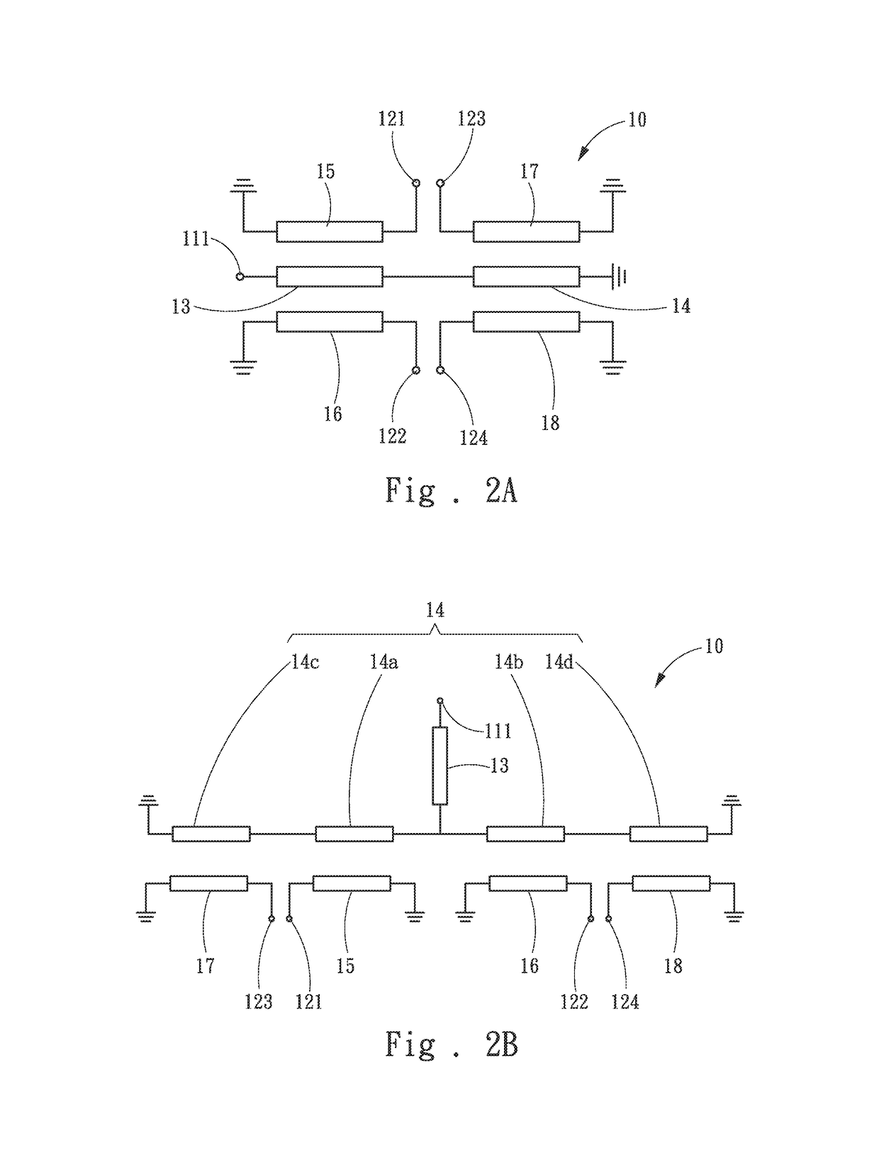
[0022]In the present invention, as illustrated in FIG. 2A, the multi-balanced-unbalanced converting unit 10 comprises a first transmission line 13, a second transmission line 14, a third transmission line 15, a fourth transmission line 16, a fifth transmission line 17 and a sixth transmission line 18. The first transmission line 13 and the second transmission line 14 are provided adjacent to each other. The first transmission line 13 is electrically connected at one end thereof to the first transmission end 111, while the first transmission line 13 is electrically connected at the other end thereof to one end of the second transmission line 14. The second transmission line 14 is electrically connected at the other end thereof to one grounding end. The third transmission line 15 and the fourth transmission line 16 are horizontally provided at top and bottom sides of the first transmission line 13, respectively. The third transmission line 15 is electrically connected at two ends ther...

second embodiment

[0024]In the practical application, coiling in a manner of planar spiral is adopted in the present invention for the miniaturization of area of each of the transmission lines formed on a substrate. Taking the aforementioned second embodiment for example, referring to FIG. 3, the multi-balanced-unbalanced converting unit 10 comprises a first transmission line 13, a second transmission line 14, a third transmission line 15, a fourth transmission line 16, a fifth transmission line 17, a sixth transmission line 18 and a connecting part 19. The first transmission line 13 comprises a first strip-type transmission line 131 situated at a central region. The detailed structure of this first strip-type transmission line will be described as follows. Referring to FIG. 4A, which is a partially enlarged diagram of left half of FIG. 3, together, the first transmission line 13 comprises a second strip-type transmission line 132, a first L-type transmission line 133 and a second L-type transmission...

third embodiment

[0032]Referring to FIG. 5, there is shown a structural diagram of a multi-balanced-unbalanced converting unit of the present invention. For widening the application of the multi-balanced-unbalanced converting unit 10 further, the structure of the multi-balanced-unbalanced converting unit of the previous embodiment is symmetrically mapped in the present embodiment, such that the second input / output ends 12, originally provided with only four transmission ends, are formed with eight transmission ends. In this way, more saturated output power than that in the previous embodiment may be obtained. The characteristics of the transmission lines are similar to those in the previous embodiment, and should not be described further.

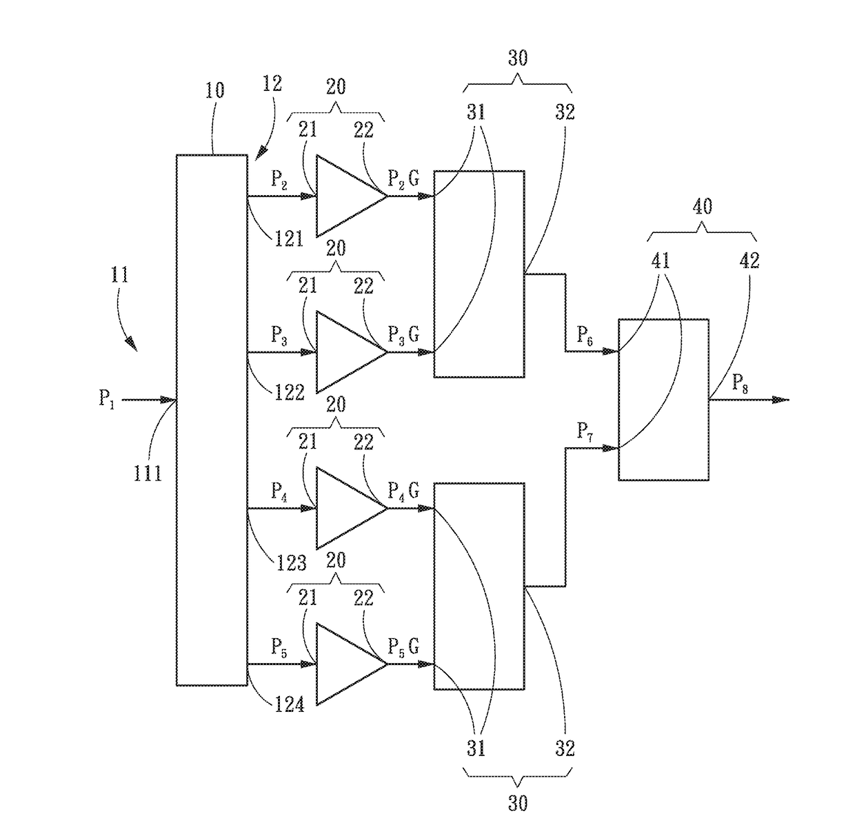
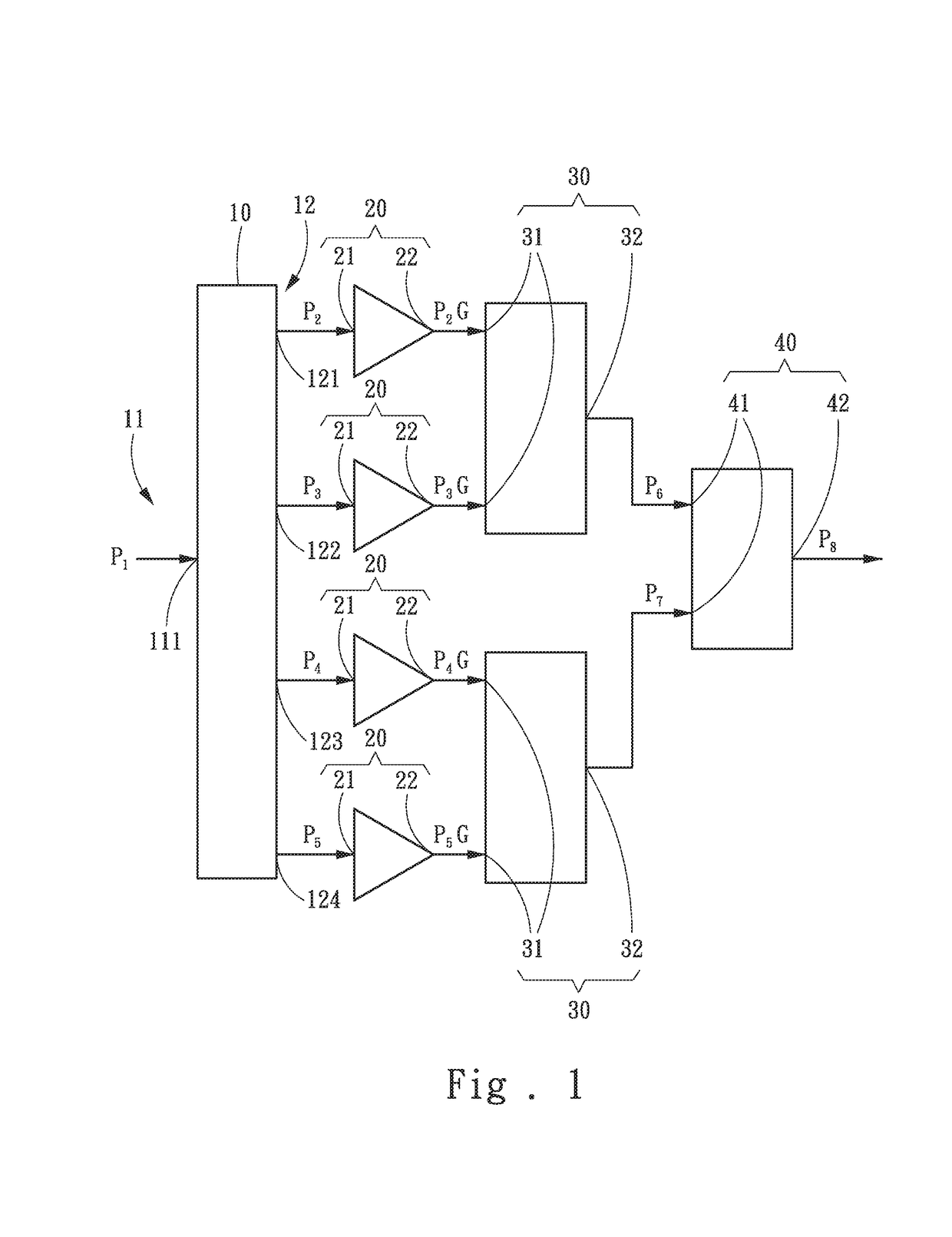
[0033]In the practical operation, taking FIG. 1 for example, an input power signal P1 is inputted to the multi-balanced-unbalanced converting unit 10 from the first transmission end 111 to be subject to balanced-unbalanced signal conversion, and then outputted from ...


PUM


Abstract

A power amplifying converter comprises a multi-balanced-unbalanced converting unit, a plurality of power amplifying units, a plurality of dual-path power combining units and a differential power combining unit. The multi-balanced-unbalanced converting unit is provided with a first input/output end and a plurality of second input/output ends. Each of the power amplifying units is provided with a first input end electrically connected to the second input/output end, and a first output end. Each of the dual-path power combining units is provided with two second input ends electrically connected to the first output ends, and a second output end. The differential power combining unit is provided with two third input ends electrically connected to the second output ends, and a third output end. In this case, the multi-balanced-unbalanced converting unit is made up of a plurality of 1/12 wavelength transmission lines.

Description

FIELD OF THE INVENTION[0001]The present invention is related to a power amplifying converter, particularly to a power amplifying converter with a balanced-unbalanced converting unit made up of 1 / 12 wavelength transmission lines.BACKGROUND OF THE INVENTION[0002]In the field of wireless transmission, types of signal transmission are primarily classified into balanced transmission and unbalanced transmission. Each type of signal transmission, however, has its own advantages and disadvantages. To solve the above problems, two types of signal transmission are further integrated by wireless communication industries to form a device having functions of balanced transmission and unbalanced transmission at the same time, such that respective disadvantages are remedied. This device is mostly made up of ¼ wavelength transmission lines.[0003]For instance, U.S. Pat. No. 6,441,696 B1 proposed a balun circuit comprising a λ / 2 waveguide, a first λ / 4 waveguide and a biasing means. A first end of the...

Claims


Application Information

Patent Timeline
Patent Type & Authority Applications(United States)
IPC IPC(8): H03H7/48H03F3/60
CPCH03F3/602H03H7/42H01P5/10H01P5/12H03F2200/198H03F2200/451
Inventor LIN, YO-SHENGLIN, YNN-WENKAO, MING-HUANG
Owner NATIONAL CHI NAN UNIVERSITY
Why Eureka
Try Eureka